26
RED LED’s, Fault or Batt lights up while in flight
Make a plan to land as soon as possible.
Find the Fault screen, which is just two > key presses from Gauge1 screen.
Press +1 in Gauge or Fault screen to attempt to clear the Fault.
Note what the Fault was and if it clears or not. If the Fault clears it may be ok to keep flying but if the Fault occurs
again or will not clear it is best to land the airplane as soon as possible to investigate the cause.
Annual maintenance
When doing spark plug checks it is a good idea at the same time to check spark plug wire resistance, should be
less than 1000 ohms for each plug wire. Reading may vary some due to carbon based coating on the surface of the
plug wire copper conductor. Higher than 1000 ohms and the plug wire should be replaced or both crimp terminals
re-crimped or replaced. Usually a bad wire will still give a reading but if resistance is too high it would be risky to
continue using the plug wire and it could be arcing inside the boot and may cause misfires at high power, but idle
just fine, not a good situation.
Do a visual check of all wiring where wires enter the white connectors at gold ecu. Look for broken or frayed wiring.
Check ground bus connections for tightness and if any corrosion. Check power wire connections to your power
switches for loose screws or loose crimp connections.
Check hall sensor wiring for physical damage where it passes through bulkheads, baffling or firewall.
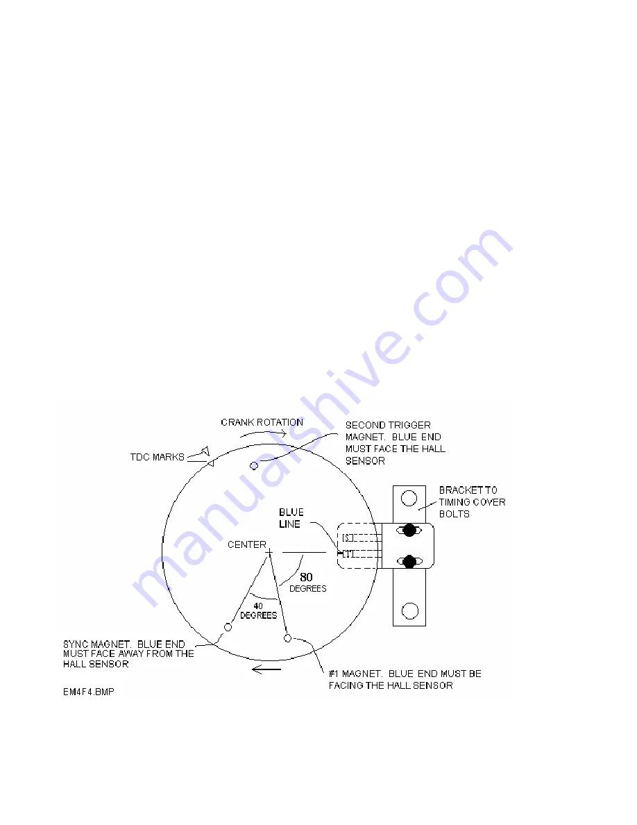
Generic Hall sensor and Magnet installation diagrams.
If you have a Lycoming consult our special supplement instead of these
diagrams below.
4 cylinder schematic drawing of hall sensor installation.


