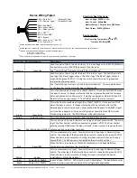
SDC S6000-101 Quick Start Manual Download Page 5

BLU (Reset)

WHT (Bypass)

RED (+)

BLK (-)

Power
Transfer

24VDC

101-1AK

REMOTE ANNUNCIATOR

BYPASS/RESET

(OPTIONAL)

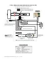
TYPICAL WIRING FOR SINGLE OR DOUBLE DOOR INSTALLATION

YEL (Rly – COM)

631RF

POWER

SUPPLY

GRN
BRN

MASTER

Power

Transfer

SLAVE

PIGT

A

IL

WHT

WHT

BLK

RED

VIO (Remote Trig)

ORG (+24VDC Out)

MC-4**
Door
Contact
(Master)

MC-4**
Door
Contact
(Slave)

GRN

WHT

GRY 
(DPS)

GRN

WHT

**Door Contact connection MC-4 
is provided with every Master 
Unit. Use for anti-tailgate, BOCA, 
door prop alarms and added 
security.

NOTE

:  Red & Blk pigtail wires are 

the minimun required connections for 
a single door application.

KEY CYLINDER INSTALLATION & OPERATION

Key cylinder is in the normal, center 
position.  LED is solid green when the 
device is secure.

To bypass the device for an extended 
period of time, momentarily turn the 
key cylinder towards “Bypass” and 
return to the center position.  LED will 
flash slowly.

When the device is in a secure state, momentarily 
turning the key cylinder towards “Reset” will result 
in a timed authorized unlock (REX).

When the device is in an alarm, authorized 
unlock, or bypassed state, momentarily turning 
the key cylinder towards “Reset” will re-secure the 
device.

P:\INSTALLATION INST\Delayed Egress\INST-S6000-101.vsd      Rev D.1    10-19     Page 5
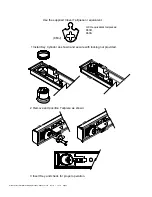
SDC S6000-101

SDC S6000-DES

INSTALL 1-1/8" MORTISE 
CYLINDER  (NOT SUPPLIED) 
INTO DEVICE COVER AS 
SHOWN ON PAGE 7.

SDC P/N:  CYL-6KDQ

Summary of Contents for S6000-101

Page 1: ...with AHJ approval Control Inputs Field selectable 1 to 30 second request to exit with anti tailgate and door prop alarm Bypass Reset Remote trigger for Pairs of Doors DPS Required for Door Forced Prop...

Page 2: ...or If an external door position switch is connected to the DPS input the door will automatically relock on door closure Authorized Maintained Bypass from a Secure state Unlocking the door for an exten...

Page 3: ...Single Door Pair of Doors WARNING CONTACT THE AUTHORITY HAVING JURISDICTION FOR APPROVAL PRIOR TO SELECTING NUSIANCE TIME OR PWR UP SETTINGS DIP SWITCH SETTINGS 1s 2s 15s 20s 30s 1s ON ON OFF 1 2 3 4...

Page 4: ...ormally Open OR Normally Closed using Jumper J7 The YELLOW wire is the relay common Green Green Relay This is the Door Secure Relay Output Dry 1A 12 24VDC It is normally ACTIVE when the door is secure...

Page 5: ...on KEY CYLINDER INSTALLATION OPERATION Key cylinder is in the normal center position LED is solid green when the device is secure To bypass the device for an extended period of time momentarily turn t...

Page 6: ...ONTROL SYSTEM C N C N O Installation Note Cap any unused leads MOV TYPICAL WIRING FOR SINGLE DOOR WITH SDC ELECTRIC TRIM SDC S6000 101 Install MOV across coil to protect device electronics J6 GRN RELA...

Page 7: ...ON INST Delayed Egress INST S6000 101 vsd Rev D 1 10 19 Page 7 1 Install Key Cylinder as shown and secure with locking nut provided 2 Remove and position Tailpiece as shown ILCO equivalent tail pieces...

Reviews: