


8. The Hi-Shear Emlock may be wire to one of two different electrical configurations. An Auto Relock time delay
(standard with the 1565) is recommended for all installations to delay relocking 1 to 6 seconds after initial door closure.
This will help ensure the door is fully closed and at rest to obtain alignment before the Emlock is energized. Consult
Figure 7A or 7B according to material supplied.
With the power off make all wire connections to a properly fused power source.
9. When installing 1566 model use Figure 7B, make the timer adjustment as required and test the TDA time delay prior to
mounting in the frame. The TDA timer is field adjustable for 1 to 6 seconds and is factory set at approximately 3
seconds. Turn clockwise to increase and counter clockwise to decrease the delay time.
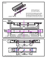
10. Install the Emlock and armature with the auto relock switch assembly towards the leading edge of the door.
11. For proper operation, the armature must be adjusted upward as close as possible and parallel to the Emlock without
interfering with opening and closing of the door. Proper operation cannot be expected with more than 1/8” clearance
between the armature and the Emlock. Use the hex key provided to adjust the armature vertical adjustment screw (the
allen head screws centered at both ends of the armature assembly). Turn counter clockwise to raise the armature.
12. With the door closed, turn the lock power on. Check the lateral alignment. The armature shear stops should be
centered between each pair of magnet shear stops.
13. If the clearance between the shear stops is sufficient, open and close the door a few times to ensure the Emlock will lock
and unlock positively.
14. Adjust the auto relock switch magnet to avoid early activation and help ensure positive locking on door closure. Adjust
inward to delay Emlock activation.
Do not
adjust higher than the armature rest position.
15. If the shear stops are too close or binding, double check the templating and door alignment, and make corrections as
required.
16. If positive locking cannot be attained due to misalignment after the previous adjustments, the armature shear stops can
be reversed with the wide clearance shear stops.
CAUTION: The use of armature offset shear stops may correct misalignment but should not be used when proper
door latching is inhibited.
17. Repeat steps 11 through 15 as necessary following shear stop replacement.
18. Cycle the door and Emlock several times after the completion of installation.
P:\INSTALLATION INST\ELECTROMAGNETIC LOCKS\INST-SHEAR 65-66\INST-SHEAR 65-66.vsd REV F 10-12 Page 2
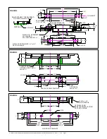
MODEL #
LOCK DIMENSION
L
W
D
10-7/116" 1-1/2”
1-5/8”
1565
1566
HOLDING
FORCE
10-7/16”
1-1/2”
1-1/4”
2700
2700
POWER
CONSUPTION
12VDC
800mA
800mA
400mA
400mA
24VDC
MODEL #
ITC
FTC
HTC
ARMATURE DIMENSION
L
W
D
11"
1-1/2”
1-1/2”
7/8”
7/8”
1-1/2”
7/8”
11"
11"