SCW NWP5204P4 User Manual Download Page 79

User Manual of Network Video Recorder

79

6.1.4 Playing Back by Tag

Purpose:

Video tag allows you to record related information like people and location of a certain time point during playback.

You are also allowed to use video tag(s) to search for record files and position time point.

Before playing back by tag:
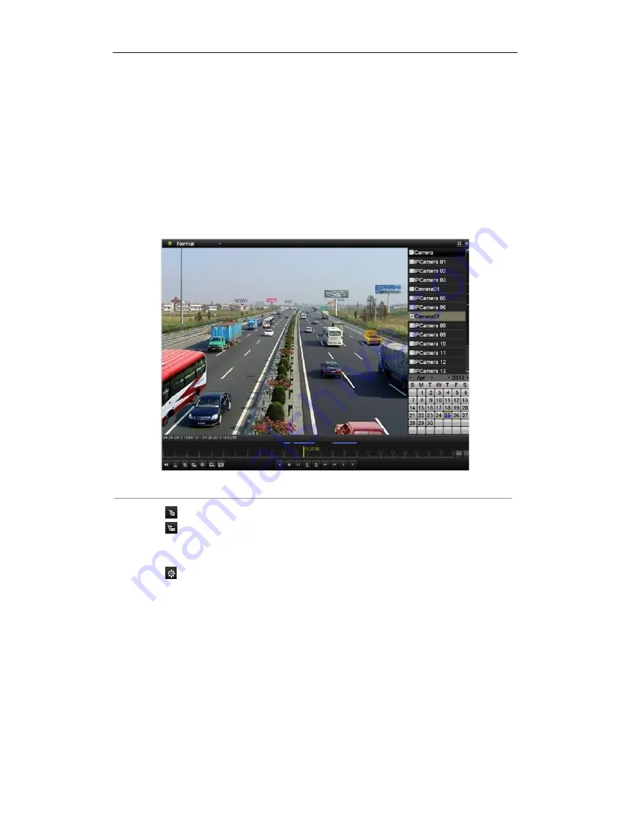
1.

Enter Playback interface.

Menu>Playback

2.

Search and play back the record file(s). Refer to

Chapter 6.1.1

for the detailed information about searching

and playback of the record files.

0.:7, 49,7-(*,5-2(>)(*1)>#03,

Click

button to add default tag.

Click

button to add customized tag and input tag name.

Note:

Max. 64 tags can be added to a single video file.

3.

Tag management.

Click

button to check, edit and delete tag(s).

Summary of Contents for NWP5204P4

Page 1: ...SCW Support 866 414 2553 User Manual for The Networker Line of NVRs NWP5204P4 NWP5208P8...

Page 2: ...ept any interference received including interference that may cause undesired operation EU Conformity Statement This product and if applicable the supplied accessories too are marked with CE and compl...

Page 3: ...s properly secured to a rack or shelf Major shocks or jolts to the unit as a result of dropping it may cause damage to the sensitive electronics within the unit Use the device in conjunction with an U...

Page 4: ...for purchasing our product If there is any question or request please do not hesitate to contact dealer This manual is applicable to the models listed in the following table Series Model Type The Net...

Page 5: ...ions Privacy mask Multiple PTZ protocols supported PTZ preset patrol and pattern Zooming in by clicking the mouse and PTZ tracing by dragging mouse HDD Management Up to 2 SATA hard disks can be connec...

Page 6: ...rating permission which includes the limit to access any channel Operation alarm exceptions and log recording and searching Manually triggering and clearing alarms Import and export of device configur...

Page 7: ...User Manual of Network Video Recorder 7 Remotely start stop recording Remotely start stop alarm output Remote PTZ control Two way audio and voice broadcasting Embedded WEB server...

Page 8: ...P series NVR 34 Chapter 3Live View 37 3 1 Introduction of Live View 38 3 2 Operations in Live View Mode 39 3 2 1 Using the Mouse in Live View 39 3 2 2 Quick Setting Toolbar in Live View Mode 40 3 3 Ad...

Page 9: ...y Normal Video Search 91 7 1 3 Backing up by Event Search 96 7 1 4 Backing up Video Clips 98 7 2 Managing Backup Devices 100 Chapter 8Alarm Settings 104 8 1 Setting Motion Detection Alarm 105 8 2 Sett...

Page 10: ...guring OSD Settings 152 11 2 Configuring Privacy Mask 153 11 3 Configuring Video Parameters 154 Chapter 12 NVR Management and Maintenance 155 12 1 Viewing System Information 156 12 1 1 Viewing Device...

Page 11: ...User Manual of Network Video Recorder 11 Appendix175 Glossary 176 Troubleshooting 177 Summary of Changes 183 List of Compatible IP Cameras 184...

Page 12: ...User Manual of Network Video Recorder 12 Chapter 1 Introduction...

Page 13: ...sed to speed up and slow down recorded video The Left and Right button will select the next and previous record files In Live View mode these buttons can be used to cycle through channels In PTZ contr...

Page 14: ...cators The corresponding indicator blinks when the HDD is being read or written 2 Panel Lock You can lock or unlock the panel by the key 3 Running Status Indicator The indicator lights when the device...

Page 15: ...channel in Live view or PTZ Control mode Input numbers and characters in Edit mode Switch between different channels in All day Playback mode 4 EDIT Button Edit text fields When editing text fields it...

Page 16: ...record files In Live View mode these buttons can be used to cycle through channels In PTZ control mode it can control the movement of the PTZ camera ENTER Button Confirm selection in any of the menu...

Page 17: ...indicator on the front panel turns blue the remote control is operating properly If the Status indicator does not turn blue and there is still no response from the remote please check the following 1...

Page 18: ...your provider The operation of the mouse 2 8 7069054 5 9 5 8 549752 Name Action Description Left Click Single Click Live view Select channel and show the quick set menu Menu Select and enter Double Cl...

Page 19: ...1 4 Input Method Description 0 7 5 9 5 7 Description of the buttons on the soft keyboard 2 8 7069054 5 9 5 9 5 7 548 Icons Description Icons Description English Capital English Numbers Symbols Lowerc...

Page 20: ...be connected when NVR starts up 7 HDMI HDMI video output connector 8 VGA DB9 connector for VGA output Display local video output and menu 9 AUDIO IN BNC connector for audio input Also for two way audi...

Page 21: ...asing No Item Description 1 Power Switch Switch for turning on off the device 2 LAN Network Interface Connector for LAN Local Area Network 3 Audio In RCA connector for voice talk input 4 GND Ground ne...

Page 22: ...User Manual of Network Video Recorder 22 Chapter 2 Getting Started...

Page 23: ...mended that an Uninterruptible Power Supply UPS be used in conjunction with the device 2 Turn on the power switch on the rear panel 3 After startup the Power LED indicator turns on supported by HNR30P...

Page 24: ...Video Recorder 24 Rebooting the NVR In the Shutdown menu you can also reboot the NVR Steps 1 Enter the Shutdown menu by clicking Menu Shutdown 2 Click the Logout button to lock the NVR or the Reboot b...

Page 25: ...on You can also choose to use the Setup Wizard next time by leaving the Start wizard when the device starts checkbox checked 2 Click Next button on the Wizard window to enter the Login window as shown...

Page 26: ...izard window as shown in Figure 2 6 HNR30P series 0 7 9 571 54 0 7 9054 Note For HNR30P series NVR the internal NIC IPv4 address should be configured for the cameras connecting to the PoE network inte...

Page 27: ...nitialization removes all the data saved in the HDD 9 Click Next button to enter the Adding IP Camera interface 10 Click Search to find online IP Camera Select the IP camera to be added and click the...

Page 28: ...User Manual of Network Video Recorder 28 0 7 57 9904 8 12 Click Copy to copy the settings to other channels as shown in Figure 2 10 0 7 56 57 9904 8 13 Click OK to complete the startup Setup Wizard...

Page 29: ...d correct For detailed checking and configuring of the network please see Chapter Checking Network Traffic and Chapter Configuring Network Detection OPTION 1 Steps 1 Right click the mouse when you in...

Page 30: ...the icons Icon Explanation Icon Explanation Edit basic parameters of the camera Add the detected IP camera The camera is connected you can click the icon to get the live view of the camera The camera...

Page 31: ...to add the camera OPTION 2 Steps 1 Enter the Camera Management interface Menu Camera Camera 0 7 04 4 2 Repeat the step 1 and 2 of adding IP cameras manually to add the camera 0 7 3 7 4 3 49 49 7 3 For...

Page 32: ...c information of the camera lists in the page you can configure the basic setting of the IP cameras Steps 1 Click the icon to edit the parameters you can edit the IP address protocol and other paramet...

Page 33: ...7 3 Click Apply to save the settings and click OK to exit the interface Configuring the customized protocols Purpose To connect the network cameras which are not configured with the standard protocol...

Page 34: ...the dropdown list please refer to Figure 2 22 0 7 7595 52 9904 3 Choose the protocols you just added to validate the connection of the network camera 2 3 3 Editing IP cameras connected to the PoE int...

Page 35: ...ed 0 7 3 7 089 Note The cameras connecting to the PoE interface cannot be deleted in this menu 2 Click the button and select the Adding Method in the drop down list Plug and Play It means that the cam...

Page 36: ...User Manual of Network Video Recorder 36 0 7 09 3 7 49 7 4 2 3 Click the Apply button to finish adding...

Page 37: ...User Manual of Network Video Recorder 37 Chapter 3 Live View...

Page 38: ...view mode there are icons at the right top of the screen for each channel showing the status of the record and alarm in the channel so that you can know whether the channel is recorded or whether the...

Page 39: ...54 04 0 0 Name Description Menu Enter the main menu of the system by right clicking the mouse Single Screen Switch to the single full screen by choosing channel number from the dropdown list Multi scr...

Page 40: ...1 9904 552 7 548 Icons Description Icons Description Icons Description Enable Disable Manual Record Instant Playback Mute Audio on PTZ Control Digital Zoom Image Settings Live View Strategy Close Inst...

Page 41: ...Settings icon can be selected to enter the Image Settings menu You can set the image parameters like brightness contrast saturation and hue 0 7 3 9904 8 89530 Live View Strategy can be selected to se...

Page 42: ...menu include Video Output Interface Designates the output to configure the settings for Only VGA HDMI is selectable by default Live View Mode Designates the display mode to be used for Live View Dwel...

Page 43: ...Select the small window and double click on the channel number to display the channel on the window You can click button to start live view for all the channels and click to stop all the live view 3...

Page 44: ...de and if you want to do some operation you need to enter user name and password tog in again Steps 1 Enter the Shutdown menu Menu Shutdown 0 7 Shutdown 2 Click Logout Note After you have logged out t...

Page 45: ...User Manual of Network Video Recorder 45 Chapter 4 PTZ Controls...

Page 46: ...Z camera Steps 1 Enter the PTZ Settings interface Menu Camera PTZ 0 7 4 7 2 2 Choose the camera for PTZ setting in the Camera dropdown list 3 Enter the parameters of the PTZ camera Note All the parame...

Page 47: ...PTZ camera to point to when an event takes place Steps 1 Enter the PTZ Control interface Menu Camera PTZ More Settings 0 7 PTZ More Settings 2 Use the directional button to wheel the camera to the loc...

Page 48: ...eset in the PTZ setting interface Steps 1 Enter the PTZ Control interface Menu Camera PTZ More Settings 2 Check the round icon of Call Preset 0 7 PTZ Call Preset 3 Choose the preset number Call preset...

Page 49: ...nu Camera PTZ More Settings 2 Select patrol number in the drop down list of patrol 3 Select the under Patrol option box to add key points for the patrol 0 7 PTZ Add Key Point 4 Configure key point par...

Page 50: ...makes the PTZ to move according the predefined patrol path Calling patrol in the PTZ setting interface Steps 1 In the PTZ setting interface Menu Camera PTZ More Settings 2 Select the patrol number an...

Page 51: ...to make the PTZ movement according to the predefined path Steps 1 Enter the PTZ Control interface Menu Camera PTZ More Settings 2 Choose pattern number in the option box 0 7 99 74 3 Click and use your...

Page 52: ...trol interface Menu Camera PTZ More Settings 2 Select the pattern number 3 Click then the PTZ moves according to the pattern Click to stop it Call pattern in live view mode Steps 1 In the live view mo...

Page 53: ...enter the PTZ toolbar 0 7 552 7 2 8 7069054 5 9 9552 7 0 548 Icon Description Icon Description Icon Description Direction button and the auto cycle button Zoom Focus Iris Zoom Focus Iris The speed of...

Page 54: ...User Manual of Network Video Recorder 54 Chapter 5 Record Settings...

Page 55: ...nstall a HDD and initialize it Menu HDD General 0 7 4 7 2 2 Check the storage mode of the HDD 1 Click Advanced to check the storage mode of the HDD 2 If the HDD mode is Quota please set the maximum re...

Page 56: ...e HDD if the deadline is reached the file will be deleted You can set the expired time to 0 and then the file will not be deleted The actual keeping time for the file should be determined by the capac...

Page 57: ...Select Record Schedule 0 7 57 2 2 Choose the camera you want to configure 3 Select the check box after the Enable Schedule item 4 Click Edit button or click on the color icon under the edit button and...

Page 58: ...he above edit schedule steps to schedule recording for other days in the week If the schedule can also be applied to other days click Copy 0 7 56 2 95 9 7 8 IV Click OK to save setting and back to upp...

Page 59: ...Recorder 59 0 7 8 70690548 5 9 5257 0 548 Click the Apply button to validate the settings If the settings can also be used to other channels click Copy and then choose the channel to which you want t...

Page 60: ...veillance center and so on In this chapter you can follow the steps to schedule a record which triggered by the detected motion Steps 1 Enter the Motion Detection interface Menu Camera Motion 0 7 5905...

Page 61: ...the motion detection event to trigger recording 6 Click Apply to save the settings 7 Click OK to back to the upper level menu 8 Exit the Motion Detection menu 3 Edit the Motion Detection Record Sched...

Page 62: ...triggered recording Steps 1 Enter the Alarm setting interface Menu Configuration Alarm 0 7 2 73 9904 8 2 Click the Alarm Input tab 0 7 2 73 9904 8 2 73 46 9 1 Select Alarm Input number and configure a...

Page 63: ...o back to the upper level menu Repeat the above steps to configure other alarm input parameters If the settings can also be applied to other alarm inputs click Copy and choose the alarm input number 0...

Page 64: ...ual settings interface Menu Manual Or press the REC button on the remote control 0 7 4 2 57 2 Enabling Manual Record 1 Select Record on the left bar 2 Click the status button before camera number to c...

Page 65: ...the record schedule on holiday for that year You may want to have different plan for recording on holiday Steps 1 Enter the Record setting interface Menu Record Holiday 0 7 520 9904 8 2 Enable Edit Ho...

Page 66: ...e different modes for the date format to configure holiday schedule 4 Set the start and end date 5 Click Apply to save settings 6 Click OK to exit the Edit interface 3 Enter Record Schedule settings i...

Page 67: ...the HDD and click to enter the Local HDD Settings interface 1 Set the HDD property to Redundancy 0 7 4 7 2 0904 2 Click Apply to save the settings 3 Click OK to back to the upper level menu Note You...

Page 68: ...68 0 7 57 7 3 9 78 2 Select Camera you want to configure in the drop down list 3 Check the checkbox of Redundant Record 4 Click Apply to save settings and back to the upper level menu Repeat the above...

Page 69: ...ting interface 4 Configuring HDD group 1 Choose a group number for the HDD group 2 Click Apply and then in the pop up message box click Yes to save your settings 3 Click OK to back to the upper level...

Page 70: ...7 2 1 2 Select the channels you want to investigate by checking the checkbox to 3 Configure the record type file type start end time 4 Click Search to show the results 0 7 2 1 7 8 29 5 Protect the rec...

Page 71: ...Managing HDD Group 3 Set the HDD property to Read only 4 Click OK to save settings and back to the upper level menu Notes 1 You can t save any files in a Read only HDD If you want to save files in th...

Page 72: ...User Manual of Network Video Recorder 72 Chapter 6 Playback...

Page 73: ...n the instant playback mode only record files recorded during the last five minutes on this channel will be played back 0 7 489 49 2 1 49 7 OPTION 2 1 Enter the Playback interface Mouse right click a...

Page 74: ...Button Operation Button Operation Button Operation Button Operation Audio on Mute Start Stop clipping 30s forward 30s reverse Add default tag Add customized tag Tag management Speed down Pause reverse...

Page 75: ...ack 2 Check the checkbox of channel s in the channel list and then double click to select a date on the calendar 0 7 2 1 2 4 7 Note If there are record files for that camera in that day in the calenda...

Page 76: ...ime line Speed up Previous day Next day Full Screen Exit Stop Digital Zoom Smart Search Video type Process bar Note Playback progress bar use the mouse to click any point of the progress bar or drag t...

Page 77: ...result 0 7 7 8 29 7 2 73 4 4 59054 5 Click button to play back the file Notes 1 Pre play and post play can be configured 2 If the event is set to trigger the recording of multiple channels clicking t...

Page 78: ...peration Audio on Mute Start Stop clipping 30s forward 30s reverse Add default tag Add customized tag Tag management Speed down Pause reverse play Reverse play Single frame reverse play Pause play Pla...

Page 79: ...es and position time point Before playing back by tag 1 Enter Playback interface Menu Playback 2 Search and play back the record file s Refer to Chapter 6 1 1 for the detailed information about search...

Page 80: ...Choose channels edit start time and end time and then click Search to enter Search Result interface Note You can enter keyword in the textbox to search the tag on your command 0 7 0 5 7 3 Click butto...

Page 81: ...everse Add default tag Add customized tag Tag management Speed down Pause reverse play Reverse play Single frame reverse play Pause play Play Single frame play Scaling up down the time line Speed up P...

Page 82: ...Click Log Search tab to enter Playback by System Logs Set search time and type and click Search button 0 7 89 3 5 7 49 7 3 Choose a log with record file and click button to enter Playback interface No...

Page 83: ...k up and play back files in the external devices Steps 1 Enter Tag Search interface Menu Playback 2 Select the External File in the drop down list on the top left side The files are listed in the righ...

Page 84: ...rder to locate motion detection event easily and accurately in the playback progress bar you are allowed to analyze a certain area scene dynamically and to get all of the related motion detection even...

Page 85: ...click button to set the full screen as target searching area After drawing area s click button to execute smart search in this area Note Multi area and full screen searching modes are supported 0 7 7...

Page 86: ...ipping 30s forward 30s reverse Add default tag Add customized tag Tag management Speed down Pause reverse play Reverse play Single frame reverse play Pause play Play Single frame play Scaling up down...

Page 87: ...nterface 6 2 4 Reverse Playback of Multi channel Purpose You can play back record files of multi channel reversely Up to 8 ch with 4CIF resolution simultaneous adverse playback is supported up to 4 ch...

Page 88: ...User Manual of Network Video Recorder 88 0 7 4 7545 8 2 1 49 7 3 Click to play back the record files reversely...

Page 89: ...User Manual of Network Video Recorder 89 Chapter 7 Backup...

Page 90: ...d files on a specified channel cannot exceed one day Otherwise the message box Max 24 hours are allowed for quick export will pop up 2 The number of channels for synchronous export cannot exceed 4 Oth...

Page 91: ...r exe will be exported automatically during record file export 0 7 1 6 5 0 1 6579 8 29 804 7 1 2 Backing up by Normal Video Search Purpose The record files can be backup to various devices such as USB...

Page 92: ...rd files you want to back up Note The size of the currently selected files is displayed in the lower left corner of the window 0 7 8 29 5 573 2 0 5 7 57 1 6 4 Export Click Export button and start back...

Page 93: ...ce until all record files are exported with pop up message box Export finished 0 7 6579 0408 5 Check backup result Choose the record file in Export interface and click button to check it Note The Play...

Page 94: ...you want to back up Click button to play the record file if you want to check it Check the checkbox before the record files you want to back up Note The size of the currently selected files is display...

Page 95: ...ce until all record files are exported with pop up message box Export finished 0 7 6579 0408 5 Check backup result Choose the record file in Export interface and click button to check it Note The Play...

Page 96: ...of Event Type Note Event types contain Alarm Input and Motion here we take the backing up by alarm input as an example 2 Select the alarm input No and time 0 7 49 7 57 1 6 2 Click Search button to ent...

Page 97: ...If the inserted USB device is not recognized Click the Refresh button Reconnect device Check for compatibility from vendor You can also format USB flash drive or USB HDDs via the device 0 7 6579 49 8...

Page 98: ...o clips to export directly during Playback using USB devices USB flash drives USB HDDs USB writer or SATA writer Steps 1 Enter Playback interface Please refer to Chapter 6 1 Playing Back Record Files...

Page 99: ...to quit and do not save video clips 0 7 99 49054 95 0 5 206 04 5 Export Click Export button and start backup Note If the inserted USB device is not recognized Click the Refresh button Reconnect devic...

Page 100: ...er player exe will be exported automatically during record file export 0 7 1 6 5 0 5 2068 6579 8 29 804 2 8 70 7 2 Managing Backup Devices Management of USB flash drives and USB HDDs 1 Enter Search Re...

Page 101: ...e a new folder in the backup device Select a record file or folder in the backup device and click button if you want to delete it Select a record file in the backup device and click button to play it...

Page 102: ...ack up Click Export button to enter Export interface Note At least one record file shall be selected 0 7 8 29 5 573 2 0 5 7 57 1 6 3 Backup device management Click Erase button if you want to erase th...

Page 103: ...User Manual of Network Video Recorder 103 0 7 709 7 4 3 49...

Page 104: ...User Manual of Network Video Recorder 104 Chapter 8 Alarm Settings...

Page 105: ...ensitivity Click button and set alarm response actions 3 Click Trigger Channel tab and select one or more channels which will start to record or become full screen monitoring when motion alarm is trig...

Page 106: ...m response actions of motion alarm please refer to Chapter Setting Alarm Response Actions Repeat the above steps to set up arming schedule of other days of a week You can also use Copy button to copy...

Page 107: ...selected alarm input Check the Enable checkbox and click button to set up its alarm response actions 0 7 2 73 46 9 9 6 49 7 3 Select Trigger Channel tab and select one or more channels which will sta...

Page 108: ...ing tab and set PTZ linkage of the alarm input Set PTZ linking parameters and click OK to complete the settings of the alarm input Note Please check whether the PTZ or speed dome supports PTZ linkage...

Page 109: ...User Manual of Network Video Recorder 109 0 7 56 9904 8 5 2 73 46 9...

Page 110: ...oss Check the checkbox of Enable Video Loss Alarm and click button to set up handling action of video loss 3 Set up arming schedule of the channel 1 Select Arming Schedule tab to set the channel s arm...

Page 111: ...1 Alarm Response Actions Repeat the above steps to set up arming schedule of other days of a week You can also use Copy button to copy an arming schedule to other days 5 Click the OK button to complet...

Page 112: ...nel Check the checkbox of Enable Video Tampering Drag the sensitivity bar and choose a proper sensitivity level Use the mouse to draw an area you want to detect video tampering Click button to set up...

Page 113: ...ponse actions of video tampering alarm please refer to Chapter Setting Alarm Response Actions Repeat the above steps to set up arming schedule of other days of a week You can also use Copy button to c...

Page 114: ...atted HDD Network Disconnected Disconnected network cable IP Conflicted Duplicated IP address Illegal Login Incorrect user ID or password Record Exception No space for saving recorded files Steps Ente...

Page 115: ...nnel settings the channel s you want to make full screen monitoring Audible Warning Trigger an audible beep when an alarm is detected Notify Surveillance Center Sends an exception or alarm signal to r...

Page 116: ...ods shall not be repeated or overlapped 0 7 9 7304 2 5 2 73 96 9 3 Repeat the above steps to set up arming schedule of other days of a week You can also use Copy button to copy an arming schedule to o...

Page 117: ...output the alarm can be cleared only by clicking Clear button in the following interface Steps Select the alarm output you want to trigger or clear and make related operations Menu Manual Alarm Click...

Page 118: ...User Manual of Network Video Recorder 118 Chapter 9 Network Settings...

Page 119: ...igure the following settings NIC Type IPv4 Address IPv4 Gateway MTU and DNS Server If the DHCP server is available you can click the checkbox of DHCP to automatically obtain an IP address and other ne...

Page 120: ...y to save and exit the interface 6 After successful settings the system asks you to reboot the device to enable the new settings and the PPPoE dial up is automatically connected after reboot You can g...

Page 121: ...49 7 DynDNS 1 Enter Server Address for DynDNS i e members dyndns org 2 In the NVR Domain Name text field enter the domain obtained from the DynDNS website 3 Enter the User Name and Password registere...

Page 122: ...can use the alias you registered in the SIMPLEDDNS server or define a new device domain name If a new alias of the device domain name is defined in the NVR it will replace the old one registered on th...

Page 123: ...n the address bar Alias refers to the Device Domain Name on the device or the Device Name on the SIMPLEDDNS server Example http www simpleddns com nvr Note If you mapped the HTTP port on your router a...

Page 124: ...ture 4 Configure the following NTP settings Interval Time interval between the two synchronizing actions with NTP server The unit is minute NTP Server IP address of NTP server NTP Port Port of NTP ser...

Page 125: ...ve and exit the interface Note Before setting the SNMP please download the SNMP software and manage to receive the device information via SNMP port By setting the Trap Address the NVR is allowed to se...

Page 126: ...239 252 0 0 to 239 255 255 255 Steps 1 Enter the Network Settings interface Menu Configuration Network 2 Select the More Settings tab to enter the More Settings interface as shown in Figure 9 14 3 Set...

Page 127: ...efault Server Port is 8000 and the HTTP Port is 80 and you can change them according to different requirements 5 Click Apply button to save and exit the interface Note The Server Port should be set to...

Page 128: ...ion Network 2 Set the IPv4 Address IPv4 Subnet Mask IPv4 Gateway and the Preferred DNS Server in the Network Settings menu 3 Click Apply button to save the settings 4 Select the Email tab to enter the...

Page 129: ...4 9 2 11Configuring UPnP Purpose Universal Plug and Play UPnP can permit the device seamlessly discover the presence of other network devices on the network and establish functional network services f...

Page 130: ...box Configure the external port No for server port http port RTSP port and https port respectively Notes 1 You can use the default port No or change it according to actual requirements 2 External Por...

Page 131: ...d function the local menu operation will be affected It is recommended to disable this function after finishing the remote downloading of record files Steps 1 Enter the Network Settings interface Menu...

Page 132: ...c to obtain real time information of NVR such as linking status MTU sending receiving rate etc Steps 1 Enter the Network Traffic interface Menu Maintenance Net Detect 0 7 9 571 7 0 49 7 2 You can view...

Page 133: ...st to start testing network delay and packet loss The testing result pops up on the window If the testing is failed the error message box will pop up as well Refer to Figure 9 30 0 7 8904 8 29 5 9 571...

Page 134: ...ck Export to start exporting 5 After the exporting is complete click OK to finish the packet export as shown in 0 0 7 1 9 6579 99 49054 Note Up to 1M data can be exported each time 9 4 3 Checking the...

Page 135: ...network parameters 9 4 4 Checking Network Statistics Purpose You can check the network status to obtain the real time information of NVR Steps 1 Enter the Network Detection interface Menu Maintenance...

Page 136: ...User Manual of Network Video Recorder 136 Chapter 10 HDD Management...

Page 137: ...88 5 5 404090 20 Click Yes button to initialize it immediately or you can perform the following steps to initialize the HDD Steps 1 Enter the HDD Information interface Menu HDD General 0 7 4 573 9054...

Page 138: ...User Manual of Network Video Recorder 138 0 7 9 9 8 4 8 95 573 2 Note Initializing the HDD will erase all data on it...

Page 139: ...own in Figure 10 6 0 7 4 573 9054 49 7 3 Add the allocated NetHDD 4 Select the type to NAS or IP SAN 5 Configure the NAS or IP SAN settings Add NAS disk 1 Enter the NetHDD IP address in the text field...

Page 140: ...N disk from the list shown below 4 Click the OK button to add the selected IP SAN disk Note Up to 1 IP SAN disk can be added 0 7 081 6 After having successfully added the NAS or IP SAN disk return to...

Page 141: ...Storage Mode interface Menu HDD Advanced 2 Set the Mode to Group as shown in Figure 10 10 0 7 957 5 49 7 3 Click the Apply button and the following Attention box will pop up 0 7 99 49054 57 559 4 Cli...

Page 142: ...ing the HDD property please set the storage mode to Group refer to step1 4 of Chapter Setting HDD Groups A HDD can be set to read only to prevent important recorded files from being overwritten when t...

Page 143: ...or Redundancy 4 Click the OK button to save the settings and exit the interface 5 In the HDD Information menu the HDD property will be displayed in the list Note At least 2 hard disks must be install...

Page 144: ...s shown in Figure 10 15 Note The NVR must be rebooted to enable the changes to take effect 0 7 957 5 9904 8 49 7 3 Select a camera for which you want to configure quota 4 Enter the storage capacity in...

Page 145: ...quota settings You can also click the checkbox of IP Camera to select all cameras 7 Click the OK button to finish the Copy settings and back to the Storage Mode interface 8 Click the Apply button to...

Page 146: ...us of each HDD which is displayed on the list as shown in Figure 10 18 0 7 0 9 9 8 Note If the status of HDD is Normal or Sleeping it works normally If the status is Uninitialized or Abnormal please i...

Page 147: ...User Manual of Network Video Recorder 147 0 7 0 9 9 8...

Page 148: ...Enter the S M A R T Settings interface Menu HDD HDD Detect 2 Select the HDD to view its S M A R T information list as shown in Figure 10 20 0 7 9904 8 49 7 The related information of the S M A R T is...

Page 149: ...you want to configure and choose All Detection or Key Area Detection as the detection type 3 Click the Detect button to start the detection 0 7 957 9 9054 And you can click Error info button to see th...

Page 150: ...Error from the dropdown list 3 Click the checkbox s below to select the HDD error alarm type s as shown in Figure 10 22 Note The alarm type can be selected to Audio Warning Notify Surveillance Center...

Page 151: ...User Manual of Network Video Recorder 151 Chapter 11 Camera Settings...

Page 152: ...terface Menu Camera OSD 2 Select the camera to configure OSD settings 3 Edit the Camera Name in the text field 4 Configure the Display Name Display Date and Display Week by clicking the checkbox 5 Sel...

Page 153: ...amera to set privacy mask 3 Click the checkbox of Enable Privacy Mask to enable this feature 0 7 70 81 9904 8 49 7 4 Use the mouse to draw a zone on the window The zones will be marked with different...

Page 154: ...ng Video Parameters Steps 1 Enter the Image Settings interface Menu Camera Image 0 7 3 9904 8 49 7 2 Select the camera to set image parameters 3 You can click on the arrow to change the value of each...

Page 155: ...User Manual of Network Video Recorder 155 Chapter 12 NVR Management and Maintenance...

Page 156: ...ure 12 1 0 7 0 4 573 9054 49 7 12 1 2Viewing Camera Information Steps 1 Enter the System Information interface Menu Maintenance System Info 2 Click the Camera tab to enter the Camera Information menu...

Page 157: ...he Alarm tab to enter the Alarm Information menu to view the alarm information as shown in Figure 12 4 0 7 2 73 4 573 9054 49 7 12 1 5Viewing Network Information Steps 1 Enter the System Information i...

Page 158: ...xport Log Files Purpose The operation alarm exception and information of the NVR can be stored in log files which can be viewed and exported at any time Steps 1 Enter the Log Search interface Menu Mai...

Page 159: ...u can click the button of each log or double click it to view its detailed information as shown in Figure 12 8 And you can also click the button to view the related video files if available 0 7 5 9 02...

Page 160: ...older button to create new folder in the backup device or click the Format button to format the backup device before log export Notes 1 Please connect the backup device to NVR before operating log exp...

Page 161: ...User Manual of Network Video Recorder 161 0 7 5 6579 49 7 You can check the checkbox of the HDD Click the Export button to export all the log files stored in the HDD...

Page 162: ...ame parameters Steps 1 Enter the Import Export Configuration File interface Menu Maintenance Import Export 0 7 36579 6579 54 0 02 2 Click the Export button to export configuration files to the selecte...

Page 163: ...he local upgrade menu as shown in Figure 12 12 0 7 5 2 6 7 49 7 4 Select the update file from the backup device 5 Click the Upgrade button to start upgrading 6 After the upgrading is complete reboot t...

Page 164: ...Network Video Recorder 164 0 7 6 7 49 7 3 Enter the FTP Server Address in the text field 4 Click the Upgrade button to start upgrading 5 After the upgrading is complete reboot the NVR to activate the...

Page 165: ...lt interface Menu Maintenance Default 0 7 8957 957 29 2 Click the OK button to restore the default settings Note Except the network parameters including IP address subnet mask gateway MTU default rout...

Page 166: ...User Manual of Network Video Recorder 166 Chapter 13 Others...

Page 167: ...g settings Language The default language used is English Resolution Select the output resolution which must be the same with the resolution of the monitor screen Time Zone Select the time zone Date Fo...

Page 168: ...teps 1 Enter the General Settings interface Menu Configuration General 2 Choose DST Settings tab 0 7 9904 8 49 7 You can check the checkbox before the Auto DST Adjustment item Or you can manually chec...

Page 169: ...me Edit the name of NVR Device No Edit the serial number of NVR The Device No can be set in the range of 1 255 and the default No is 255 The number is used for the remote and keyboard control Auto Log...

Page 170: ...unts Purpose There is a default account in the NVR Administrator The Administrator user name is admin 13 4 1Adding a User Steps 1 Enter the User Management interface Menu Configuration User 0 7 8 7 4...

Page 171: ...no permission of Two way Audio in Remote Configuration and only has the local remote playback in the Camera Configuration User s MAC Address The MAC address of the remote PC which logs onto the NVR If...

Page 172: ...g deleting and editing of the IP cameras Remote Serial Port Control Configuring settings for RS 232 and RS 485 ports Remote Video Output Control Sending remote button control signal Two Way Audio Real...

Page 173: ...ring factory default parameters 13 4 2Deleting a User Steps 1 Enter the User Management interface Menu Configuration User 2 Select the user to be deleted from the list as shown in Figure 13 8 0 7 8 7...

Page 174: ...09 8 7 49 7 4 Edit the user information including user name password level and MAC address Check the checkbox of Change Password if you want to change the password of the current user 5 Click the OK...

Page 175: ...User Manual of Network Video Recorder 175 Appendix...

Page 176: ...S is a method protocol or network service that provides the capability for a networked device such as a router or computer system using the Internet Protocol Suite to notify a domain name server to ch...

Page 177: ...ning sound Di Di Di DiDi after a new bought NVR starts up Possible Reasons a No HDD is installed in the device b The installed HDD has not been initialized c The installed HDD is not compatible with t...

Page 178: ...onnected Possible Reasons a The IPC and the NVR versions are not compatible b Unstable power supply of IPC c Unstable network between IPC and NVR d Limited flow by the switch connected with IPC and NV...

Page 179: ...er to do the further process Live view stuck when video output locally Possible Reasons a Poor network between NVR and IPC and there exists packet loss during the transmission b The motion detection a...

Page 180: ...y change according to the real condition and check if there exists packet loss Note Simultaneously press Ctrl and C to exit the ping command 3 Verify the hardware of the PC is good enough Simultaneous...

Page 181: ...lution of 720p the frame extracting may occur which leads to a slight stuck Steps 1 Verify the network between NVR and IPC is connected 1 When image is stuck connect the RS 232 ports on PC and the rea...

Page 182: ...Playback and verify the channel and time are correct 3 Verify the HDD status is normal Select Menu HDD General to view the HDD status and verify the HDD is detected and can be read and written normall...

Page 183: ...by the right click menu Chapter 2 3 1 2 Support smart search function Chapter 6 2 2 3 Support connecting the third party network cameras from Brickcom and Bosch Appendix List of IP Cameras Compatible...

Page 184: ...305M 65175 1280 1024 AV2155 65143 1600 1200 AV2815 65220 1920 1080 AV3105M 65175 1920 1080 AV5105 65175 1920 1080 AXIS M1114 5 09 1 1024 640 M3011 ONVIF compatibility 5 21 704 576 Only AXIS is support...

Page 185: ...cation 1 30 Image data 2 21 1280 960 WV SW559 ONVIF compatibility Application 1 30 Image data 2 21 1920 1080 WV SW558 ONVIF compatibility Application 1 30 Image data 2 21 1920 1080 WV SW355 ONVIF comp...

Page 186: ...124 ONVIF compatibility 1 73 00 1280 720 SNC EP580 ONVIF compatibility 1 53 00 1920 1080 SNC DH220T Only ONVIF is supported 1 50 00 2048 1536 Vivotek IP7133 0203a 640 480 FD8134 ONVIF compatibility 01...

Reviews: