


IN
AU
STRAL
IA
PR
OU
DLY BUILT
3
INSTRUCTIONS -
VIEWMASTER PRO
Projection Screen
Continued Over.../
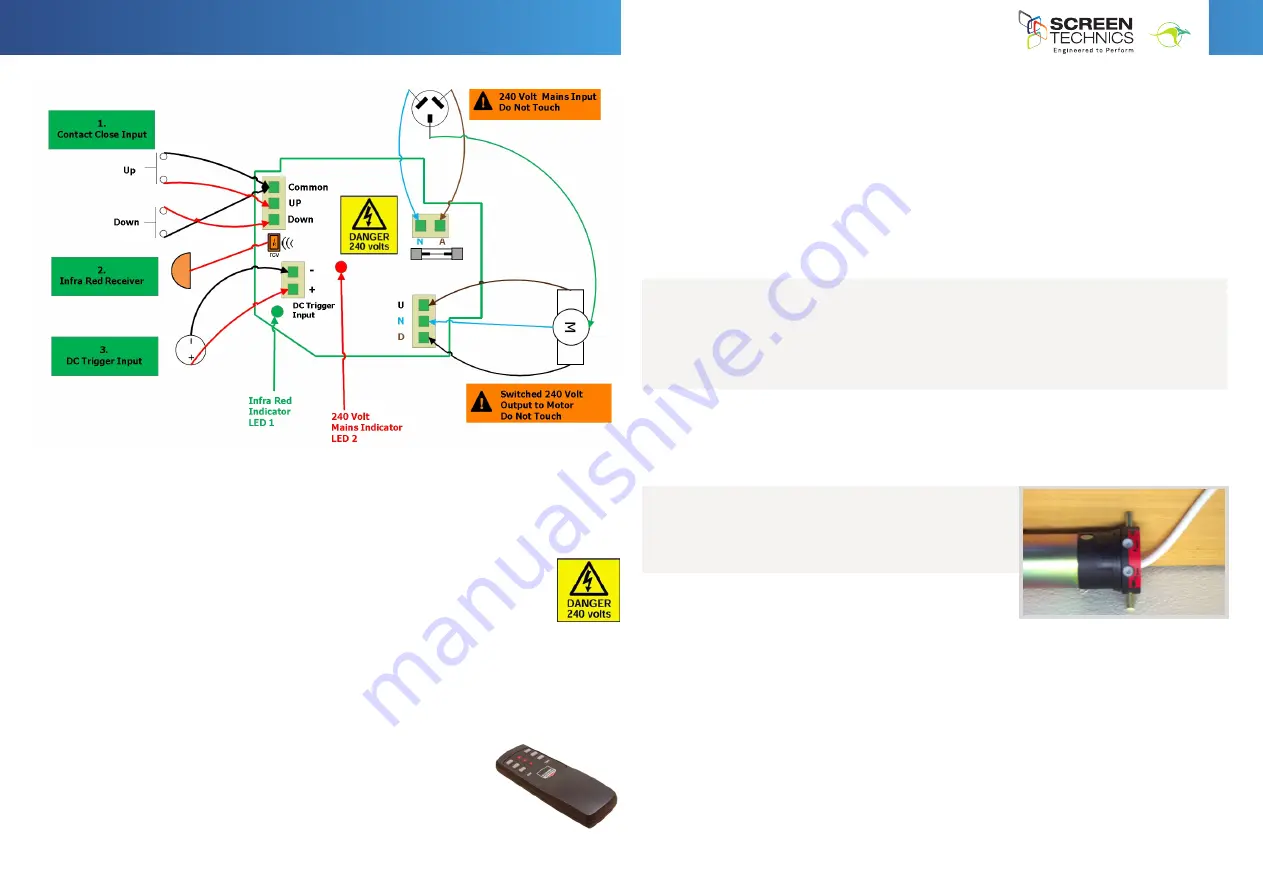
1. CONTACT CLOSE INPUT
•
No voltage, dry contact input
•
Requires momentary contact only
•
Contact is closed and opened between Up & Common – screen moves to up limit
•
Contact is closed and opened between Down & Common – screen moves to bottom limit
•
Stop command is sent when both Up & Down contact closed together
•
Motor reverses travel when opposite contact is closed – if moving down and up contact is
closed screen will stop and then reverse direction
•
Stop command is sent when both Up & Down contact closed together
2. INFRA-RED RECEIVER
•
Packaged with 300mm and 1.2 M lead from motor board to IR receiver
•
Packaged with standard 2 channel IR transmitter
•
Screen operates on group 1 & 2 on infra-red remote
•
Green LED 1 on motor board will flash when IR commands are received
3. DC TRIGGER INPUT
•
Down command is sent when a DC Voltage above 1.5 Volts @ 1mA minimum is applied to
trigger input
•
Up command is sent when a DC Voltage below 1.5 Volts @ 1mA minimum is applied to the
trigger input
•
Trigger input is polarity sensitive
•
DC voltage must not exceed 15 Volts DC
Note: The Viewmaster pro is equipped with automatic retraction after power failure, if power is
lost to the screen, the surface will retract to the up position when power is reconnected
MasterFit IP A, A+, B, B+, C, C+ Projection Screen
Thank you for purchasing a Screen Technics Projection Screen, please ensure that you read
the following instructions fully before installing this product.
The motor controller for the MasterFit range of projection screens is housed in an insulated
box and is packaged with a 1.2M IEC mains flex with moulded 3 pin plug and 240 volt output
to motor is supplied with a 4 pin WAGO connector with a 4M long 4 core flex allowing
placement flexibility.
1.
Contact Close Input
No voltage, dry contact input
Requires momentary contact only
Contact is closed and opened between Up & Common – screen moves to up limit
Contact is closed and opened between Down & Common – screen moves to bottom limit
Stop command is sent when both Up & Down contact closed together
2.
Infra-Red Receiver
Packaged with 300mm and 1.2 M lead from motor board to IR receiver
Packaged with standard 2 channel IR transmitter
Screen operates on group 1 & 2 on infra-red remote
Green LED 1 on motor board will flash when IR commands are received
Access to control board is on left hand side of projector screen case
Power must be removed before accessing inputs on control board
1.
Contact Close Input
No voltage, dry contact input
Requires momentary contact only
Contact is closed and opened between Up & Common – screen moves to up limit
Contact is closed and opened between Down & Common – screen moves to bottom limit
Motor reverses travel when opposite contact is closed – if moving down and up contact is closed
screen will stop and then reverse direction
Stop command is sent when both Up & Down contact closed together
2.
Infra-Red Receiver
Packaged with 300mm and 1.2 M lead from motor board to IR receiver
Packaged with standard 2 channel IR transmitter
Screen operates on group 1 & 2 on infra-red remote
Green LED on motor board will flash when IR commands are received
3.
DC Trigger Input
Down command is sent when a DC Voltage of 1.5 Volts @ 1mA minimum is applied to trigger input
Up command is sent when a DC Voltage below 1.5 Volts @ 1mA minimum is applied to the trigger input
Trigger input is polarity sensitive
DC voltage must not exceed 15 Volts DC
Note: The Viewmaster pro is equipped with automatic retraction after power failure, if power is lost to the
screen, the surface will retract to the up position when power is reconnected
Access to control board is on left hand side of projector screen case.
Power must be removed before accessing inputs on control board.
LIMIT SETTING FOR VIEWMASTER PRO SCREENS
The following instructions are for the adjustment of the limit switches that alter the upper
and lower stop positions on “Connect” ElectriCinema Screens only
WHERE ARE THE LIMIT SWITCHES?
(On the Left Hand Side).
One switch is accessible through the slat rod opening and the other is behind round cover plug
towards the front of the canister.
WHICH SWITCH IS FOR UP AND DOWN?
Down switch - Accessible through the round cover plug
Up switch - Accessible through the slat rod opening
WHAT TOOLS DO I NEED?
Either the limit setting tool (supplied), a narrow tip
screw driver (less than 4mm) or a 4mm Allen Key
RJ12 6 Core Straight Through Data cable can link up to 8 Connect controlled devices for multiple switching.
Low Voltage Trigger
Switches device upon the receipt of 3v to 24v DC from a projectors low volt output port, plugs into the phoenix
connector on the module.
Not polarity sensitive.
IP Control RJ45
Due to the detailed nature of the user instructions associated with this method of control we direct you to the
associated document – Electricinema IP Control Instructions V1.0
However for a beginners guide to basic control functions please download from
www.screentechnics.com.au
the PC Connect or Mac Connect software and this will assist you in identifying the Connect Module and provide
basic control, then guide you by web browser to communicate and program the individual Module.
Note: You will have to connect the screen module to a network to be able to utilise this software.
Note: As the Infra-Red control is also used to perform a Connect module reset in case you are troubleshooting any performance
issues, it is recommended that the IR cable be left attached to the module even if it is not the chosen operating method for your
installation.
Limit Setting for Connect ElectriCinema Screens
The following instructions are for the adjustment of the limit switches that alter the upper
and lower stop positions on "Connect" ElectriCinema Screens only
Where are The Limit Switches?
At the opposite end to the power cable (ie on the Right Hand Side).
One switch is accessible through the slat rod opening and the other is behind a rubber grommet
towards the front of the canister.
Which Switch is for Up and Down?
Down switch - Accessible through the rubber grommet
Up switch - Accessible through the slat rod opening
What Tools do I Need?
Either the limit setting tool (supplied), a narrow tip screw driver (less than 4mm) or a
4mm Allen Key
Which Way do I Turn the Switch?
Clockwise always increases the amount of rotation (travel) of the motor.
Anti-clockwise always reduces the amount of rotation (travel) of the motor.
So pick the switch responsible for the limit position, up or down. Clockwise turning of the switch will always let the motor travel
further in that direction. Anti-clockwise turning of the switch will lessen the amount of travel in that direction.
Can I adjust the switch while the screen is sitting on the limit - ie fully up or down?
Clockwise adjustment? – YES. But it is better to back the screen away from the limit and then adjust
Anti-clockwise adjustment? - NO you will damage the micro switch if you turn it anti-clockwise while the screen is sitting on the limit.
Never attempt this. You must back the screen away from the limit
before adjustment. After adjustment you will need to run the screen up and down to pick up the new limit
Will I void the product warranty if I damage the screen whilst making these adjustments?
Yes.


