


2
IN
AU
STRAL
IA
PR
OU
DLY BUILT
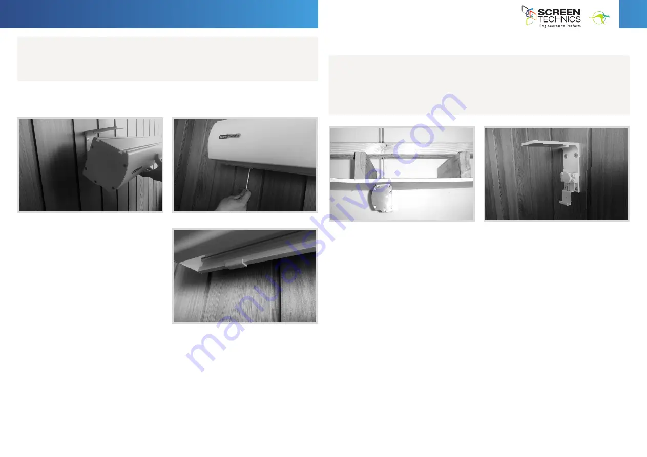
STEP 6.
Holding screen in position tighten up Allen screw at each end and check that the top
pins have hooked into the T section of the screen canister.
IMPORTANT.
Always ensure that you can
remove the screen for maintenance or repair
if required. Do not sheet it in place.
•
Ensure that the screen is free to descend and that any adhesive tape that has been placed
bottom of the screen (to stop movement during transport) has been fully removed.
•
When installed, the opening in the canister should be down and at the back of the canister.
This will put the chain drive on the left-hand side of the screen, as viewed by the audience.
(Unless ordered otherwise).
•
Cleaning of the screen is best achieved by first dusting the surface with a feather duster,
then to remove any stubborn marks, use a small amount of mild detergent and warm water
on a clean white lint free cloth. Do not use a saturated cloth, as this may leave a watermark,
only a damp one. It is most important that you only treat the actual mark by this process
and not the entire surface.
The Motor is 240 V 50Hz and draws 1.2 A.
The screen drop is set and tested at the factory. Therefore, any damage caused to the screen
from limit re-adjustment is not covered by warranty.
Should you have any questions regarding the installation of our projection screens please call
our technical sales desk on +61 2 4869 2100 for assistance.
Please follow these instructions to ensure trouble free operation;
CEILING MOUNT INSTRUCTIONS
Below is a photo showing a side view using the brackets for ceiling fixing, you would follow the
instructions for the wall mounting system, with the only difference being the screen is mounted
hard against the ceiling. It is important that adequate support is supplied by the ceiling
structure to support the screen and to ensure a safe installation. Never rely just on the Gyprock
for attachment.
STEP 5.
Using two people install the screen by placing the screen canister into the bottom of
the bracket clips and pivoting back the canister to slot the top pins into the T channels running
along the top of the canister (you may have to remove any tape that is in the way).
INSTRUCTIONS -
ELECTRICINEMA TYPE A, B & C
Connect IP Projection Screen
Continued Over.../


