65
Electrical System
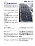
Press the remote switch once to engage the bat-
tery switch. A light in the switch will illuminate
to indicate that the battery switch is ON. To turn
the battery switch OFF, press and hold the switch
for 3 seconds. The LED light may not turn off im
-
mediately or will slowly fade out if there are no
loads present on the system. This is normal as
the capacitors in the system drain.
To operate the battery switches remotely in Auto
Mode, the manual knob on each battery switch
must be set to “AUTO OFF.” In this position,
each battery switch will move from “AUTO OFF”
to “AUTO ON” when the remote switch is turned
on and from “AUTO ON” to “AUTO OFF” when the
remote switch is turned off. LED lights at the re
-
mote switches and on each battery switch will be
lit when the battery switches are in the ON posi-
tion. The LED lights at the remote switches and
on the battery switches will be off and the battery
switches will indicate “AUTO OFF” when the battery
switches are turned off. Remote operation of the
battery switches is not possible when they are set
to Manual Mode. If auto operation is attempted,
the LED lights will flash for 3 seconds, then stop.
The knob on the battery switches must be set to
“AUTO OFF” before they can be activated remotely.
The remote operation of the battery switches can
be overridden at anytime by depressing the control
knob on the battery switch and turning it to the
“MAN ON” or “MAN OFF” position. The “MAN ON”
LED light on the battery switch will be lit whenever
the battery switch is activated in Manual Mode.
The knob on the battery switch must be returned
to the “AUTO OFF” position before the battery
switch can be activated remotely. For more infor-
mation on the motorized battery switches, refer
to the switch manufacture’s operation manual.
When in port or at anchor, the engine battery
switches should be off. Only the battery switch
that activates the house battery bank should be
on. This will keep both engine starting batteries
in reserve for starting the engines. If the house
batteries become discharged to the point that the
accessories will not operate, the engines can be
started to recharge the house battery bank.
Notice:
Current is supplied to the automatic switch
for the bilge pump when the batteries are
connected and the battery switches are off.
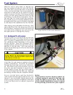
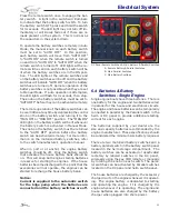
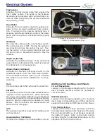
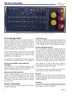
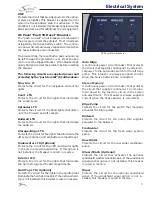
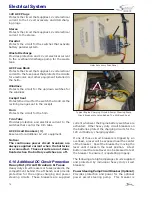
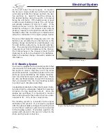
A. Remote Battery & Parallel Switches
B. Main Parallel Switches
C. Main Battery Switches
DC Panel Remote Switches & Main Battery & Parallel Switches
A
B
C
6.4 Batteries & Battery
Switches - Single Engine
Single engine boats have three batteries. There is
one battery for the engine and two batteries wired
in parallel for the house and electronics circuits.
The engine and house batteries can be temporarily
connected in parallel by the Parallel switch in the
helm or DC panel to provide additional starting
current for each engine.
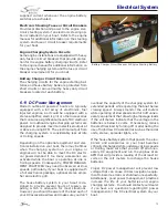
The batteries supplied by your dealer are the
size and capacity batteries recommended by the
engine manufacturer. These specifications should
be considered the minimum size battery required.
There are two motorized battery switches and a
battery parallel switch in the battery switch panel
located in the helm storage compartment. The
battery switches can be activated or deactivated
remotely by labeled switches in the DC panel,
wirelessly using the key FOB remote or manually
by rotating the knob on each switch. The paral-
lel switches can be activated by Parallel switches
located on the DC panel and helm switch panel.
The house batteries are charged by the accessory
charge circuit on the engine whenever it is operat-
ing. The engine battery is dedicated to starting
and operating the engine. It is charged by the
engine whenever it is operating. The engine and
house batteries are also charged by the battery
charger when plugged into shore power.
Summary of Contents for 255 DORADO
Page 1: ...1 Owner s Manual 255 DORADO Scout Boats Inc 2531 Hwy 78 West Summerville SC 29483 ...
Page 2: ...2 Rev 0 Print Date 9 20 2017 ...
Page 12: ...12 NOTES ...
Page 18: ...18 NOTES ...
Page 27: ...27 Operation ...
Page 62: ...62 NOTES ...
Page 112: ...112 NOTES ...
Page 116: ...116 NOTES ...
Page 124: ...124 NOTES ...
Page 130: ...130 NOTES ...
Page 134: ...134 Schematics Raw Water System Raw Water Washdown Raw Water Pump Raw Water System ...
Page 143: ...143 143 Appendix C Maintenance Log Hours Date Dealer Service Repairs ...
Page 144: ...144 Maintenance Log Hours Date Dealer Service Repairs ...
Page 145: ...145 Maintenance Log Hours Date Dealer Service Repairs ...
Page 146: ...146 Maintenance Log Hours Date Dealer Service Repairs ...
Page 147: ...147 Maintenance Log Hours Date Dealer Service Repairs ...
Page 148: ...148 Maintenance Log Hours Date Dealer Service Repairs ...
Page 149: ...149 149 Appendix D ...
Page 150: ...150 Boating Accident Report ...
Page 151: ...151 Boating Accident Report ...
Page 152: ...152 NOTES ...
Page 154: ...154 NOTES ...
Page 159: ...159 ...
Page 160: ...160 ...
Page 161: ...161 Scout Boats Inc 2531 Hwy 78 West Summerville SC 29483 ...

