background image

To Replace the Evaporator:
(Assuming all the steps for removal of the
thrust bearing, breaker, auger, and water seal
have been performed.)
1. Discharge the refrigerant from the ice
maker.
2. Unsweat the refrigerant connections:
 a) At the thermostatic expansion valve outlet.
//////////////////////////////CAUTION///////////////////////////
Heat sink the TXV body when unsweating
or
 resweating the adjacent tubing.
//////////////////////////////////////////////////////////////////////////
 b) At the suction line at the joint about 3" from
the evaporator.
3. Remove the evaporator.
4. Unsweat the drier from the liquid line.
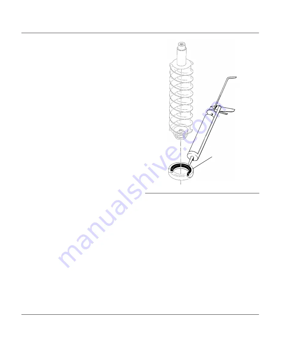
5. After installing a new water seal in the new
evaporator ( see “To Replace the Water Seal”)
resweat the tubing connections.
6. Install an new drier in the liquid line.
7. Evacuate the system until dehydrated, then
weigh in the nameplate charge.  Check for
leaks.
8. Install auger, breaker, breaker bearing
assembly, and ice discharge chute in reverse
order of disassembly.  See “To Reassemble
Evaporator and Auger”
To Reassemble the Evaporator and Auger
1. After the gearmotor has been inspected,
fasten the evaporator to the gear motor, be
sure that the number of shims indicated on the
gear case cover is in place between the
gearcase cover and the drip pan gasket.
Torque the bolts to 110 inch pounds.
2. Lower the auger into the evaporator barrel,
slightly turning it to match up with the drive
end. Do Not Drop Into the Evaporator.
3. Complete the reassembly by reversing the
disassembly for the breaker & thrust bearing
assembly.

PLACE A BEAD
OF FOOD GRADE
SEALANT HERE

REMOVAL AND REPLACEMENT: Evaporator

Head Pressure Control Valve 
1. Purge system of refrigerant
2. Break off process tube on the top of the
OLD head pressure control valve.
3. Unsweat old valve from tubing.
4. Unsweat old dryer from tubing.
5. Install new valve in place, check for correct
connections and be sure the number on the
side of the valve is “220"
6. Wrap the new valve body in wet cloths to
heat sink the valve body.
7. Sweat in the new valve and the new dryer.
8. Evacuate the system, and weigh the
nameplate charge into the receiver.

Charging Procedures
Extra care must be taken when recharging this
remote system. No liquid refrigerant may be
placed in the system at the compressor. DO

NOT use the schrader valves at the front of
the unit for weighing in the charge. All liquid
R-502 must be weighed into the receiver
through the “front seated” king valve.

NM950R

May, 1989

Page 34

Summary of Contents for NM950R

Page 1: ...ectronic circuit for monitoring ice and water level a thermostatic expansion valve and R 502 as the refrigerant TABLE OF CONTENTS For the Installer Specifications 2 Location 5 Remote Condenser 6 For t...

Page 2: ...ndenser Junction Box Electrical Inlet Water Inlet 3 8 Flare Drain 3 4 FPT 2 96 3 5 25 20 84 Allow 6 above machine for service Minimum Circuit Ampacity is used to determine wire size and type per Natio...

Page 3: ...s are designed and manufactured with the highest regard for safety and performance They meet or exceed the standards of UL NSF and CSA Scotsman assumes no liability or responsibility of any kind for p...

Page 4: ...ine set 40 R 502 KCMR230 Fan Relay Kit used when two 230 volt 32 icemakers are on one 230 volt 32 two circuit condenser DIMENSIONS H X W X D MODEL USE WITH MINIMUM CIRC AMPACITY BASIC ELECTRICAL RC105...

Page 5: ...eveling later Return the bin to the upright position remove paper covering the bin gasket Install the bin top according to the directions with the bin top Note Do not push bin into position but lift i...

Page 6: ...tions 1 Each set of precharged refrigerant lines either 25 foot or 40 foot consists of a 3 8 inch diameter liquid line and a 1 2 inch diameter discharge line Both ends of each line have quick connect...

Page 7: ...a definite increase in resistance is felt 4 Using a marker or pen mark a line lengthwise from the coupling union nut to the bulkhead Then tighten the coupling and additional 1 4 turn As the nut turns...

Page 8: ...INSTALLER Location TWO UNITS ON ONE CONDENSER REMOTE CONDENSER EXCESS PRECHARGED TUBING INSIDE BUILDING ICEMAKERS SERVICE ACCESS SERVICE ACCESS SIDE AND BACK ROOF CUTAWAY WALL CUTAWAY NM950R May 1989...

Page 9: ...the gravity type and 1 4 inch per foot fall is an acceptable pitch for the drain tubing There should be a vent at the highest point of the drain line and the ideal drain receptacle would be a trapped...

Page 10: ...r the compressor and the fan motor operates whenever the compressor operates Electrical connections are made at the junction box at the back of the icemaker and at the junction box on the remote conde...

Page 11: ...will be required 1 Mount the control box in a convenient location 2 Attach a solid earth ground wire to the ground screw 3 Route connecting wires from the first ice maker junction box marked condense...

Page 12: ...his after start up 2 Test with a volt meter between terminals 2 and 4 then between terminals 1 and 3 Compare the readings obtained to the ones in the following list C Test terminals 1 2 Full Voltage 2...

Page 13: ...INSULATED PRECHARGED REFRIGERANT TUBING A typical installation should generally appear as illustrated below The remote condenser must be located above the icemaker and the precharged lines installed...

Page 14: ...of 20 psig 7 Has the machine been secured to the bin 8 If two units on one condenser has the relay kit been installed 9 Is there a water shut off valve installed near the machine 10 Is the remote con...

Page 15: ...e electrical start up sequence is now on automatic A There should be a short 15 second delay before the gearmotor starts B After the gearmotor starts the liquid line valve will open the low pressure c...

Page 16: ...l shut the machine off it there is none Ice Discharge Chute Directs the ice produced by the evaporator into the storage bin Ice Level Sensor An electronic eye it senses the presence of ice in the bott...

Page 17: ...cuit board Pump Down Control An automatic reset pressure switch connected to the low side of the refrigeration system Controls the compressor Potential Relay The compressor start relay On Off Switch M...

Page 18: ...e auger motor is run by the circuit board for 2 5 more minutes clearing out ice in the evaporator and then The auger motor relay opens and the auger motor stops If the ice level sensor is clear bin em...

Page 19: ...r which it enters through the float valve The water them goes out the bottom of the reservoir tank to the bottom of the evaporator Reservoir overflow or evaporator condensation is routed to the drain...

Page 20: ...ding upon the temperature of the evaporator warmer evaporators get more refrigerant and colder evaporators get less At the evaporator the refrigerant enters an area of relatively low pressure where it...

Page 21: ...refrigerant into the condenser with a small amount of discharge gas going into the receiver to maintain pressure until the head pressure is built back up to the rated gauge pressure of 220 psig At tha...

Page 22: ...At this point the refrigerant flow is stopped by the closed liquid line valve This action forces the refrigerant into the receiver and keeps it out of the compressor The pump down continues until the...

Page 23: ...ic and Hydroxyacetic acids These compounds are corrosive and may cause burns If swallowed DO NOT induce vomiting Give large amounts of water or milk Call Physician immediately In case of external cont...

Page 24: ...he top bearing in the breaker should also be checked at least two times per year Check the breaker bearing by removing the ice chute cover unscrewing the ice sweep removing the water shed using a span...

Page 25: ...lacement of these parts see REMOVAL AND REPLACEMENT Shut off the water supply 1 To remove the auger remove the front and top panels 2 Remove 3 hex studs holding ice chute cover to ice chute and remove...

Page 26: ...ure control valve it should be maintaining a head pressure above 220 psig If the unit has the correct charge and the condenser is clean and the refrigerant lines are not kinked or twisted and the cond...

Page 27: ...hould be ON if not replace the circuit board If the bin full light on the tester is ON move the tester switch to bin empty the light on the tester should go OFF and the bin empty light on the circuit...

Page 28: ...move the gearbox and Check for internal damage repair and replace in the machine b Check for low charge add some refrigerant if the unit begins to operate normal low side pressure being about 30 psig...

Page 29: ...be restricted defective or not adjusted properly If needed replace the TXV evacuate and recharge per nameplate 4 Check the insulation on the evaporator It should be dry with no wet spots or frost If...

Page 30: ...cemaker 8 Reverse to reassemble BIN CONTROLS Ice Level Sensors 1 Disconnect electrical power 2 Remove front panel 3 Remove control box cover 4 Locate ice chute at the base of the chute in front of and...

Page 31: ...ews holding breaker to evaporator d Lift up and remove breaker bearing assembly from auger evaporator 6 Service the bearing Check for rust rough spots and damage a The bearing is pressed into the brea...

Page 32: ...nscrew auger stud from top of auger c Unscrew 4 allen head cap screws holding breaker to evaporator d Lift up on breaker to remove from auger If the auger is stuck Use a slide hammer type puller to pu...

Page 33: ...place the snap ring and pull the water seal down against it 3 The part of the water seal that rotates with the auger must also be replaced Remove the old part from the auger and clean the mounting are...

Page 34: ...ase cover is in place between the gearcase cover and the drip pan gasket Torque the bolts to 110 inch pounds 2 Lower the auger into the evaporator barrel slightly turning it to match up with the drive...

Page 35: ...GEAR OUTPUT SHAFT AND BEARINGS GASKET GEARCASE DRIVE MOTOR BEARING SEAL WATER SHED SEAL REMOVAL AND REPLACEMENT Gearmotor Assembly WARNING Disconnect Electrical Power Before Begining NM950R May 1989 P...

Page 36: ...rfill Note The gears and bearings are available only as pressed together sets D After replacing parts as required if any reassemble the gearcase The two smaller gears and the oil should be in the lowe...

Page 37: ...f while inspection shows that the ice level sensors are properly aligned clean and not obstructed use the tester as follows Bin Control Note All testing is done with the electrical power on the master...

Page 38: ...board should go ON If not replace the circuit board b Move the water switch on the tester to the Water position The No Water light on the board should go OFF If not replace the circuit board If the li...

Reviews: