background image

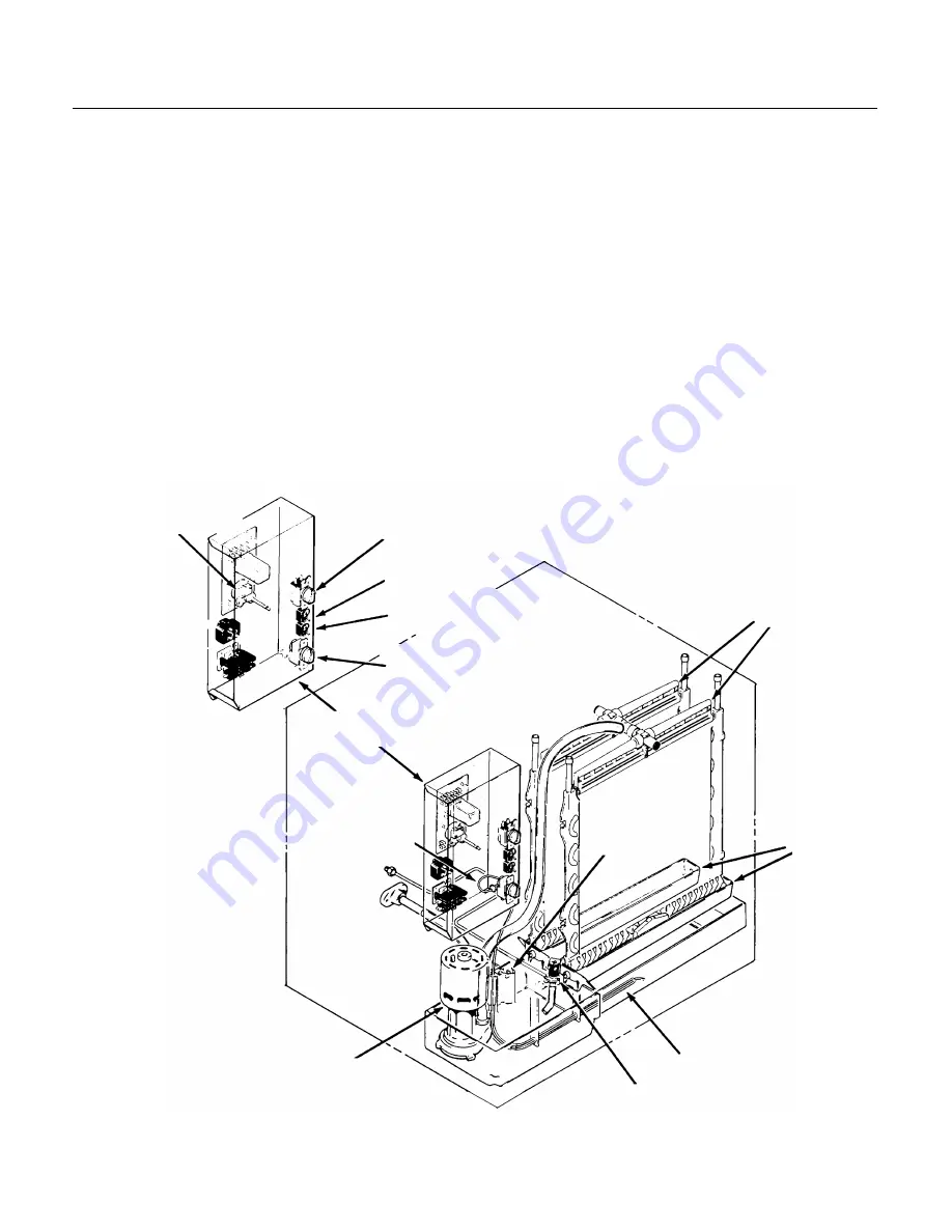
COMPONENT LOCATION

The ice machine is designed for front service.
Many components are serviceable from the front
without removing the side panels:

Behind the front panel:

••

Water pump

••

Inlet water valve

••

Reservoir

••

Evaporators

••

Water distributor

••

Control box with cube size control adjustment

••

ON/OFF switch

••

Compressor switch

Inside the control box is the control system for the
ice machine.

Timer

Cube Size Control

Master Switch

Compressor Switch

Bin Thermostat

Water

Distributors

Drain Trough

Bin Thermostat Bracket

Water Inlet Valve

Water Pump

Bin Thermostat

Control Box

Component Location

Overflow

Standpipe

CME500R

March 1994

Page 10

Summary of Contents for CME500R

Page 1: ...R THE ELECTRICIAN 7 FOR THE PLUMBER 8 FINAL CHECK LIST 9 COMPONENT LOCATION 10 COMPONENT DESCRIPTION Control System 11 COMPONENT DESCRIPTION Water System 12 INITIAL START UP 13 FREEZING CYCLE OPERATION 15 HARVEST CYCLE HOT GAS BYPASS 16 CLEANING SANITIZING 17 SYSTEM SPECIFICATIONS 19 ADJUSTMENTS 20 SERVICE DIAGNOSIS Water 21 SERVICE DIAGNOSIS Electrical and or Adjustments 22 SERVICE DIAGNOSIS Refr...

Page 2: ...nents not specifically approved by Scotsman Scotsman reserves the right to make design changes and or improvements at any time Specifications and designs are subject to change without notice FOR THE INSTALLER The CME500R will fit the following Scotsman ice storage bins BH550 HTB500 HTB350 HTB250 BH800 with bin top KBT23 BH900 with bin top KTB22 BH1360 It will also fit these Scotsman Dispensers CD2...

Page 3: ... the water is very important in obtaining pure ice and in maximizing product life The water to the ice machine should be filtered Water filters vary greatly in ability and function Install one that filters out suspended solids to a dimension of 5 microns or less The finer the filter the better but finer filters may plug up sooner than course ones It may be necessary to add a course filter ahead of...

Page 4: ...into the hole in the base of the machine 3 Locate and uncoil a portion of the bin thermostat capillary tube Route the end of the capillary tube into and through the bin thermostat bracket tube It should be inserted the full length of the tube but not past the end Stacking This machine will stack onto any CM250 CME250 CM450 CM500 CME500 CM650 or CME650 with the same cabinet depth 24 Note Stacking r...

Page 5: ...ant lines consists of a 3 8 inch diameter liquid line and a 1 2 inch diameter discharge line Both ends of each line have quick connect couplings the end without access valves goes to the icemaker Note The openings in the building ceiling or wall listed in the next step are the minimum sizes recommended for passing the refrigerant lines through 2 Have the roofing contractor cut a minimum hole for t...

Page 6: ...l Connections 3 Begin tightening the couplings together by hand then using two wrenches it is important that ONLY the nut on the precharged lines be turned the other parts of the couplings must NOT be allowed to turn or the process will tear out the diaphragms and they will be loose in the refrigeration system tighten the coupling until it bottoms out or a definite increase in resistance is felt 4...

Page 7: ...esponsible for serious damage to the icemaker The remote condenser is designed to be powered from the ice machine There is a separate electrical junction box at the back of the ice maker for the remote condenser Wire the remote condenser to the ice maker in accordance with local and national electric codes All outdoor wiring must be in rain proof conduit The condenser fan motor will run whenever t...

Page 8: ... gives about the best overall performance DRAIN Connections All drains are gravity type and must have a minimum of 1 4 inch fall per foot on horizontal runs The drains to be installed to conform with the local plumbing code Install a vertical open vent on drain line high point to insure good draining The ideal drain receptacle is a trapped and vented floor drain Recommended bin drain is 5 8 inch O...

Page 9: ...nnections been made 8 Is the water supply line shut off valve installed and electrical wiring properly connected 9 Check all refrigerant lines and conduit lines to guard against vibration or rubbing and possible failure 10 Have the bin and cabinet been wiped clean 11 Has the Manufacturers Registration form been properly filled out Check for correct model and serial numbers from Serial nameplate th...

Page 10: ...rators Water distributor Control box with cube size control adjustment ON OFF switch Compressor switch Inside the control box is the control system for the ice machine Timer Cube Size Control Master Switch Compressor Switch Bin Thermostat Water Distributors Drain Trough Bin Thermostat Bracket Water Inlet Valve Water Pump Bin Thermostat Control Box Component Location Overflow Standpipe CME500R Marc...

Page 11: ...ssembly The function of the timer begins when activated by the cube size control The outer surface or large diameter lobe of the timer cam determines the timer cycle for finish freezing of the ice cubes while the inner surface or small diameter lobe determines the time cycle for the harvest cycle When the microswitch button is pushed in there is power connected to the coil of the relay and the uni...

Page 12: ... evaporator where it enters the water distribution system Water Distribution System The water distribution system evenly supplies water to all cells of the evaporator plates The water pump pumps water from the sump up the vertical tygon tube to the tee From there water is channeled through the water manifold to the water distributors above each evaporator plate and from six holes within each distr...

Page 13: ...to start the timer The timer starts when the actuator arm on the microswitch drops off outer cam into cam slot See Front View of Timer 6 Move the Master ON OFF switch to the ON position 7 Allow the reservoir to fill If needed rotate the timer clockwise a to begin another harvest cycle to add more water to the reservoir Note Some water will drip off the evaporators this is normal and there will be ...

Page 14: ...ut longer harvest cycles Do NOT adjust harvest time too short as this will cause a freeze up of the evaporators To Adjust Harvest Time A Disconnect electrical power B Locate timer cam in the control box C Loosen set screw holding the two halves of the cam together and rotate the front half to increase or decrease the harvest portion of the cam low part D Re tighten the set screw E Reconnect power ...

Page 15: ...reezing cycle The timer will keep the icemaker operating in the freezing cycle for a selected length of time This will give the ice cubes time to fully form After that selected length of time the timer will switch the icemaker into the harvest cycle through the contacts of the timer assembly microswitch Low Temperature Freeze When the outside air temperature is low the Head Pressure Regulator will...

Page 16: ...released ice cubes drop into the ice storage bin below At the end of the harvest cycle the timer cam will push the actuator arm to the microswitch IN If the ice level control is still CLOSED a whole new cycle will begin If the ice level control is OPEN the icemaker will begin to shut OFF Pump Down Cycle When the ice level control is open at the end of the harvest cycle power is removed from the li...

Page 17: ... ON 16 Replace the front panel 17 Discard the next batch of cubes to make sure all of the acid sanitizer is gone CAUTION DO NOT use ice cubes produced from the cleaning or sanitizing solutions Be sure none remain in the bin 18 Pour hot water into the storage bin to melt the cubes and also clean out the bin drain 19 Wash the bin liner with a solution of household bleach 1 ounce of bleach to 2 gallo...

Page 18: ...s of Scotsman Ice Machine Cleaner to 4 pints of hot 950 F to 1100 F water 2 Remove all ice from the bin 3 Using rubber gloves dip a nylon scouring pad into the cleaning solution and scrub the scale off of the liner 4 After the scale has been removed rinse all of the surfaces inside the bin with clean potable water To sanitize the bin and ice machine Follow local codes for frequency of sanitizing U...

Page 19: ...set at 2 66 minutes may be adjusted to suit local conditions Typical Suction Pressure in Harvest 90 PSIG 70o F air and 50o F water 110 PSIG 90o F air and 70o F water Typical Discharge Pressure in Harvest 200 PSIG 70o F air and 50o F water 240 PSIG 90o F air and 70o F water Typical Compressor Amp Draw 10 13 freeze 14 16 harvest High Pressure Cut Out Cuts out at 450 PSIG manual reset Pump Down Press...

Page 20: ...re a corresponding adjustment of the cube size control Rotating the shaft of the timer cam clockwise will allow putting the machine into either the freezing cycle or harvest cycle as required in the cleaning instructions To Adjust The Timer Switch Assembly The length of the harvest cycle can be changed by loosening the set screw on the cam and then rotating the shaft so that the opening between th...

Page 21: ...Freeze Cycle Inlet water valve leaks through Replace inlet water valve See electrical adjustment See electrical adjustment Makes thick ice freezes up Water inlet valve restricted Clean or replace valve Low water pressure Check water filter or supply Cubes too large Inlet water valve leaks through Replace inlet water valve See electrical adjustment See electrical adjustment Low Capacity Incoming wa...

Page 22: ...ater valve Timer stuck Replace timer Relay does not energize unit stuck in harvest Replace relay Long freeze cycle Water inlet valve leaks through Replace inlet water valve Water temperature too high Advise user Cubes too small Cube size set wrong Adjust cube size Cubes size control stuck closed Replace cube size control Cubes too large Water inlet valve leaks through Replace inlet water valve and...

Page 23: ...plate charge Hot gas valve leaks thru At the end of the freeze cycle there should be frost on the evaporator end of the hot gas tubes if not replace the hot gas valve Liquid and discharge lines are in contact with each other Separate and insulate them Unit shuts off before bin is full Bin thermostat adjusted to open too soon Rotate knob on the thermostat clockwise to a colder setting Compressor cy...

Page 24: ...nt for the left water distributor tube and notch also that the distributor manifold connections at the top center of each evaporator plate is snug against the top of the plate Cube Size Control To remove the cube size control 1 Remove front panel 2 Remove cover from control box 3 Trace capillary tube from the cube size control to the refrigerant suction line 4 Remove the coiled capillary tube bulb...

Page 25: ...sen and remove outlet water line from the inlet water solenoid valve assembly 3 Remove screws and pull the water solenoid valve out to gain access 4 Pull electrical cord from solenoid coil terminals 5 Remove inlet water fitting from the water solenoid valve To replace the inlet water valve assembly reverse the removal procedures 6 Reverse to reassemble Electrical Shock Hazard Electrical shock can ...

Page 26: ... this valve be certain that the valve is the cause of the problem 2 Remove the top service and front panels 3 Discharge and recover the refrigerant 4 Unplug the coil of the valve 5 With the refrigeration system open unsweat the valve from the tubing 6 Place the new valve in position 7 Wrap the new valve body with wet rags Do not get any moisture in the valve 8 Carefully braze the valve to the tubi...

Page 27: ... equipment is required to locate small refrigerant leaks Usually a leak detector capable of detecting a Halogenated refrigerant or HFC 134a will work Check with the leak detector manufacturer if in doubt As with any other refrigerant do NOT mix HP62 with pressurized air when leak testing Pressure Temperature Chart for HP62 VAPOR VAPOR TEMP PRESSURE TEMP PRESSURE DEG F PSIG DEG F PSIG 20 17 70 146 ...

Page 28: ...refrigerant there is a leak and it must be found and repaired This system has a critical charge it must be recharged with the correct amount of refrigerant as listed on the nameplate of the ice machine or performance will suffer Anytime the refrigeration system has been opened the dryer should be replaced Note Only a HFC type dryer should be used When brazing the tubing connections to components s...

Reviews: