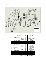
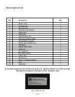
Scotchman PRESSPRO 176MT Manual Download Page 13

PAGE 13 

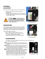
4.1.4 Pressure gauge

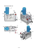
4.1.6 Speed setting valve

The speed setting valve is located in the top
cover of the hydraulic unit.

If the lever is in the lower position, the piston

will move with low speed when the directional

control valve is activated. If the lever is in the
upper position, the piston will move with high
speed when the direction control valve is
activated. When the piston is reaching the

work piece with high speed, it will

automatically switch to low speed as soon as

it feels counter pressure. This has no
influence on the maximum working pressure

or working force.

Fig. 12 Speed setting valve

The pressure gauge is located in the head (in front toward the top) of the press. The gauge shows
the pressure in psi & bars. For this press the maximum pressure is as follows:

If this maximum pressure is reached, the maximum capacity of the press is reached as well.

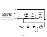
4.1.5 Pressure regulation valve

Fig. 11 Pressure regulation

Adjusting the pressure:

    Start the hydraulic unit.
    Raise the press ram so no force is applied.
    Turn the knob on the pressure control valve
    counter clockwise to lower the pressure.
     Do not remove the knob!!
      Note that it can be turned far enough to unscrew from the pressure control valve.
    Lower the press ram to the work piece and keep force applied with the joystick.

  Slowly turn the knob on the pressure control valve clockwise & carefully raise the
    pressure while watching the pressure gauge.

The pressure regulation valve is located in the top cover of the

hydraulic unit. With this valve the maximum pressure, referring

to the maximum press capacity, can be changed.  Turning the

knob clockwise will increase the pressure, turning the knob

counter clockwise will reduce the pressure.
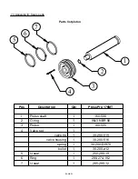
4.1.7 Hand pump

The press is equipped with a hand pump, located on the front panel of
the hydraulic unit. This pump can be used for manual pressing
functions or when accurate force setting is necessary.

To use the hand pump:

Fig. 13 Hand pump

TURN OFF the hydraulic unit by pushing the red button of the
on/ off switch.

Set the directional control valve in the required position
(up- or downwards).

Start pumping the hand pump with its lever.

PRESSURE

GAUGE

PressPro 176MT: 3700psi (255 bar)

Summary of Contents for PRESSPRO 176MT

Page 1: ...www scotchman com PRESSPRO MODEL 176MT SCOTCHMAN IND 180 E US HWY 14 PO BOX 850 PHILIP SD 57567 Phone 1 800 843 8844 VERSION 2 January 2022 MOVABLE TABLE...

Page 2: ...he machine to the floor 8 3 5 Installation of the hydraulic unit 9 3 5 1 Connecting hydraulic hoses 9 3 6 Oil tank filling 10 3 7 Electrical connection 11 4 Functions of the press 11 4 1 Hydraulic uni...

Page 3: ...emes 19 7 3 Appendix III Spare parts 21 Fig 1 Technical specifications PressPro Model 176 MT 5 Fig 2 Bolting the machine to the floor 8 Fig 3 Installation of the hydraulic unit 9 Fig 4 Securing Hydrau...

Page 4: ...s symbol to prevent damages to the machine or injury to the operator In case of doubt please contact your local supplier The supplier of the press can not be held responsible for any damages or injuri...

Page 5: ...I 4hp 176 176 3698 5 15 3 4 1 875 27 6 15 HL46 094 29 37 50 60 3000 54 5000 11 02 4 92 6 3 USA STANDARD US tons psi in gal min in sec in sec in sec delivered with an extra cylinder extension to reach...

Page 6: ...secured in place Tighten nuts bolts and screws to keep the equipment in good working condition Note the supplier of the press can not be held responsible for any damages or injuries when the machine i...

Page 7: ...aintenance has not been done by qualified personnel The press is not complete or non original spare parts have been used Any worn parts are visible The specifications of the power supply are not confo...

Page 8: ...possible 3 4 Bolting the machine to the floor Note When press is delivered check for freight damage before signing anything If you later find anything damaged while unpacking or setting up the press S...

Page 9: ...onnecting hydraulic hoses Fig 5 Hydraulic hoses and attachment locations Once the hydraulic unit is mounted the hoses must be attached The caps in the hose and fitting are color coded In the example s...

Page 10: ...nd bring it back up to the upper position Turn off the hydraulic unit Remove the filler plug again and check oil level If needed add more hydraulic oil to the tank Replace the filler plug To properly...

Page 11: ...an be changed by swapping 2 of the incoming phases SEE BELOW NOTE check if the turning direction of the motor is in the direction of the arrow looking at the motor from above THE WRONG DIRECTION CAN D...

Page 12: ...n if the lever is positioned downwards the press ram of the cylinder will move downwards As long as the valve is operated the press ram will move When the lever is released the press ram will stop and...

Page 13: ...ress ram so no force is applied Turn the knob on the pressure control valve counter clockwise to lower the pressure Do not remove the knob Note that it can be turned far enough to unscrew from the pre...

Page 14: ...time or when maintenance of the hydraulic unit is performed the hand pump needs to be de aerated To do this Start with the piston in the upper position Make sure there is no work piece on the table Tu...

Page 15: ...orce can be applied as described in the previous chapters When pressing operations are finished Return the piston back to its outer upper position Position the cylinder back to the centre of the machi...

Page 16: ...table position Section 5 3 explains how to change the position of the cylinder from side to side The cylinder on the PressPro 176 MT can be moved front to back as well This is done by anchoring the fo...

Page 17: ...t in injuries to the maintenance operator 6 1 Oil tank draining Replace the hydraulic oil at least once a year A drain plug is located at the bottom of the oil tank If the inside of the tank is not cl...

Page 18: ...C1DXX SCHNEIDER LRDXX SCHNEIDER LINE POWER START BUTTON Brown Black Blue Follow Instruction Sheet In Motor Box If Provided Brown TO MOTOR SET OVERLOAD TO FLA SHOWN ON SERIAL NO PLATE W2 U2 V2 U1 V1 W1...

Page 19: ...1M 1OL T2 INCOMING SUPPLY BY CUSTOMER PROVIDE MAXIMUM UPSTREAM PROTECTION PER N E C CODE 430 52 AND TABLE 430 152 GND 95 96 1OL E STOP 1 2 1PB START 3 4 2PB A2 1M A1 1M 13 14 L1 L3 L2 SEE MOTOR TAG F...

Page 20: ...PAGE 20...

Page 21: ...1 2 3 4 Piston shaft O ring Piston Valve set valve tip valve housing spring bullet 5 6 7 U seal Ring U seal 1 1 1 1 1 1 1 1 1 1 1 1 2 3 4 7 6 5 Qty PressPro 176MT 160 506 96x3 NBR 90 160 505 30 200 51...

Page 22: ...8 U seal 9 Complete piston assy 10 Bow grip assy 11 Label eye protection 12 Roller shaft assy Bow grip Screw Shaft 13 Roller Cotter pin Ring Piston head Screw Qty 1 2 4 1 1 4 1 1 1 1 1 1 2 1 4 1 1 2 4...

Page 23: ...s Roller bearing Bowed cover right Screws Bowed cover left Screws Roller bearing Circlip ring 1 1 3 1 1 4 4 1 4 1 2 2 2 4 4 2 2 2 2 4 4 PPTL 160 30 200 213 53 63 M4x40 100 160 627 160 200 3kW 25 M6 TL...

Page 24: ...PAGE 24 Parts list hydraulic unit...

Page 25: ...tor Handle speed setting valve Filling plug Handle control valve Drain plug On Offswitch Emergency button Cabel Plug Bell housing Pipes couplings package Tank Sight glass 1 1 1 1 1 1 1 1 1 1 1 1 1 1 1...

Reviews: