ScopeDome.com
2010 Slupsk - Poland
Shutter drive assembly
A
C
B
D
E
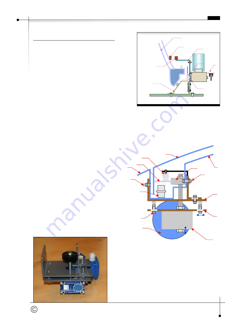
Fig. 10 - Encoder module on motor axis
A. Dome's side panel
B. Base ring.
C. Shield holder/support
D. Home sensor magnet
E. Home sensor contractron
F. Encoder module
page 7
G
F
E
D
F
C
B
A
G
H
I
J
J
K
L
M
L
B
A
C
M
Fig. 11 - Shutter drive.
A. Motor/Engine
B. Motoreductor (i=80)
C. Cog-wheel
D. Shutter holder roller
E. Cog-rim
F. Shutter's main roller
G. Dome's side panel
H. Shutter panel
I.
Dome's back panel
J. Bolts/Screws fastening the motor
K. Roller pressure adjustment screws
L. Motor main holder
M. Motor module support.
fig. 12 - Shutter drive.
Shutter drive assembly
Action sequence.
1. Screw on motor main holder (L) at dome's top with
the use of five screws.
2. Fix the cog-wheel (C) in drive motor module (M).
3. Screw on slightly drive motor with main shutter
holder in a way that the cog-wheel would not touch
shutter's cog-rim.
4. Adjust cog-wheel height so that cog-rim is at its
middle point.
5. Fix end switches.
6. Test limit switches operation trying to set them active
at approx. 2cm before full open/close of the shutter.
7. Press and tighten cog-wheel to shutter's cog-rim and
screw on the bolts (K) fastening motor module.
8. Install motor and limit switches wiring.
9. Open and close the shutter several times using
ScopeDome USB Card.
10. If the cog-wheel slips off cog-rim - stop the shutter at
this point. Loosen screws fastening the motor
module, then tighten the cog-wheel to cog-rim hitting
2X motor mounting plate with a hammer. Next screw
on firmly four bolts fastening the motor module.
11. Test shutter drive operation again.
12. Check if the shutter power cable does not brush
dome's engine during its revolution.
Shutter motor is powered by 14-core cable. Its both ends
shall be fixed firmly - as not to be teared out if the dome
proceeds too many turns. The cable shall be placed in a
way it would not brush the dome's engine.
EN
F


