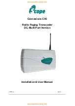
ConneXions CX5 DC, Multi Port Version
CX5DCred
Issue 2
Page
3 of 13
System Overview
Section 1: Installation
The information contained in this Section is intended for use by authorised system
installation engineers only. Unqualified personnel should not undertake installation of this
equipment under any circumstances whatsoever.
Siting of the hardware
Before locating the hardware in any given location, it is important to take into account the range of
operation that you require to obtain from your system. The standard transmitter can quite easily
provide ranges of up to a mile or more and will provide excellent propagation on most sites, covering
a considerable area with just a 1/4 wave antenna (BNC terminated) connected directly to the unit.
For coverage where exceptionally difficult operating conditions exist, it may be advantageous to
install an external antenna. Installing the transmitter on the second or third floor of a building will
more often than not boost overall range. However, horizontal range is not always required as much
as propagation through a multi storey building. Here it may be more useful to use a small external
antenna mounted outside the building at half the building height. Sometimes range is required more
in one direction than in the other: moving the aerial to one side of the building can provide a bias in
the required direction, which may overcome the range difficulties. (See section:
Other Antennas).
Important:
coaxial feeds greater than 5 metres must employ low loss 50 ohm coax. We normally do
not recommend feeds of more than 15 metres for standard applications. However, we suggest you
contact our technical dept where other considerations may prove this to be impractical.
A further consideration is the distance between the transmitter and the source of the data. If the unit
is to deploy a standard RS232 serial interface, reliable reception of the data should not be attempted
in excess of
15 metres
of cable. These cables should be screened/shielded and must be kept clear
of sources of induced magnetic or electrical noise. In the event that distances of over 15 metres are
required, additional drivers or amplifiers must be installed at both ends of the data link.
The Scope Connexions 5 is a POCSAG data display radio paging system which can be used to
transmit both text and numeric messages direct to pocket pagers carried by individuals or entire
groups. Information is input using either or both of the two RS232 serial ports. There are also models
available which provide an additional RS232 port, a USB port, an RS485 port and an ethernet port.
Contact your Scope dealer for further details. Up to 9,999 pagers can be supported on any one
system.
Note ! This system requires a valid OFCOM radio licence for operation in the UK
.
It is the user’s responsibility to apply for a Private Business Radio Licence, normally a Simple Site
Licence, available online at www.ofcom.org.uk.
Technical information to assist in completing the application:
Antennas provided by Scope are
Omni-Directional
, with a gain of
0 dB.
Equipment Type: Base Station. ERP level:
2W max.
For other EC countries, referral must be made to the relevant national telecommunications authority,
who will provide licensing details and applicable frequencies.


