Scilogex DM0636 User Manual Download Page 22

USER MANUAL 


Rotor type 

ID 

code 

Tube/bottle 

Adapter 

Max. 

speed 
(rpm) 

Max.centrifugal radius 

r

max

(cm) 

Max. RCF 

Rcf (×g) 

AS30-2 

2/1.5ml 

×

30 


6000 

10 

4020 

0.2ml 

×

30 

A02P2 

6000 

8.5 

3415 

0.5ml

×

30 

A05P2 

6000 

3618 

AS60-2 

2/1.5ml 

×

60 


6000 

10 

4020 

0.2ml

×

60 

A02P2 

6000 

8.5 

3415 

0.5ml

×

60 


A05P2 

6000 

3618 

AS18-5V 

5

mlV

×

18 


6000 

10 

4020 

AS12-PCR8 

8-PCR 

×

12 


6000 

10 

4020 

0.2ml

×

96 


6000 

10 

4020 

AS6-50V 

50mlV

×


6000 

10.7 

4306 

A30-15 

15mlV

×

30 


4500 

R1=14.2 

R2=12.2 

3210 
2760 

A8-50 

15mlV

×

16 

50mlV

×

8


5000 

12.4 

3460 

SE4-100A 

100ml 

×

4


4000 

15.9 

2840 

85ml 

×

4


A85P100 

4000 

15.9 

2840 

50mlV 

×

4


A50VP100 

4000 

15.9 

2840 

15mlV 

×

8


A15VP100 

4000 

15.1 

2700 

3

10ml 

×

8


A10P100 

4000 

14.7 

2630 

S2-MP 

(dimension

mm 

MTP 

(128

×

85.6

×

15) 


4000 

12.1 

2160 

Cell culture 

(128

×

85.6

×

21) 


4000 

12.1 

2160 

DWP


(128

×

85.6

×

45)


4000 

12.1 

2160 

Kits 

(128

×

85.6

×

60) 


4000 

12.1 

2160 

* :

15mlV means 15ml conical tube, as well as 5mlV and 50mlV. 

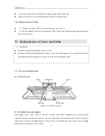
Table 11.1 Rotors and adapters 


11.1.3 Notice 

(1)  The  centrifuge rotor can separate  sample which density lower than 2.0g/ml, if  the samples density is 

over 2.0g/ml, please calculate allowable speed depending on the following formula. 

      Allow Speed (rpm)= Maximum speed×(2.0(g/ml)/Sample density (g/ml))

1/2 

2

To prevent corrosion, remove the rotor from rotor chamber if do not use for a long time, then detach the 

rotor lid and upside the rotor down to dry the tube holes. 

Summary of Contents for DM0636

Page 1: ...DM0636 Multi purpose Centrifuge Before using centrifuge please carefully read this user manual for its efficient operation and safety...

Page 2: ...ect the rotor 8 7 5 Symmetrically load centrifuge tubes in rotor 8 8 Operation 8 8 1 Normal Operation 8 8 2 RCF Operation 12 8 3 Pulse Operation 12 9 Maintenance 12 9 1 Cleaning 12 9 2 Consumables 13...

Page 3: ...USER MANUAL 2...

Page 4: ......

Page 5: ...y be reproduced or transmitted without prior written permission of original manufacture We can not be responsible to inform at real time if the outline and specifications of centrifuge is subject to c...

Page 6: ...death CAUTION Possible damage to instrument Caution notes indicate any condition or practice which if not strictly observed or remedied could result in damage or destruction of the instrument NOTE Not...

Page 7: ...orizontal before running Make sure the angle between the door and cover is greater than 70 degrees when open the door Be careful not put your fingers or hands between the door and cover when the door...

Page 8: ...emperature detector Imbalance protection Automatic internal diagnosis Power requirements Single phase 220V 240V 50Hz 60Hz 8A 110V 120V 50Hz 60Hz 12A Dimensions mm L 280 W 364 H 266 Weight 30kg Additio...

Page 9: ...ich case the user will be required to correct the interference 3 Required Operational Condition 3 1 Basic operational Conditions 1 Power Single phase 220V 240V 50Hz 60Hz 8A Single phase 110V 120V 50Hz...

Page 10: ...at least 30cm behind it to guarantee the cooling efficiency 4 Keep away from heat or water to avoid sample temperature issues or centrifuge failures 4 2 Connection of the power cord and grounding WAR...

Page 11: ...Open lock key Press the key to open the door The key is not available when the centrifuge is running 3 Start Stop key Press the key to start running The centrifuge will brake to stop running if press...

Page 12: ...is 9 memory program is 7 When speed symbol is rotating indicating the centrifuge is running the rotation is faster the speed is higher Temperature only displays the temperature of chamber and can not...

Page 13: ...erwise the rotor may be moved off while rotating and cause damage of the centrifuge and rotor Firmly tighten the rotor door with rotor 8 Operation CAUTION Do not push or lean against the centrifuge wh...

Page 14: ...00rpm Running time 30 minutes The door lock is released 8 1 1 Load and replace the rotor Figure 8 2 Load the rotor CAUTION Attach the rotor to the rotor shaft Ensure the rotor is in position and conne...

Page 15: ...peed symbol will flash the speed value The minimum speed value you can set 300rpm the minimum increment is 100rpm Rotate parameter key clockwise to increase speed value rotate the parameter key anti c...

Page 16: ...normal operation mode and run according to the new value If the set time value has been modified the operation time is not affected and will continue 3 Warning display If an error occurs during the o...

Page 17: ...the power switch and load the rotor to the shaft tighten the rotor lid and make sure it is in secured position and then close the door 2 The centrifuge gets into preparation mode and displays last ru...

Page 18: ...mple leaks in the rotor rinse the rotor with water Apply a thin coat of silicon grease to the rotor when it is completely dry The rotor should be regular maintenance recommend to cleaning it each 3 mo...

Page 19: ...n the table firmly 2 Check if the centrifuge grounded properly Use multi meter to check if is short circuit between the power cord grounding pin and the motor shaft If yes indicating grounded properly...

Page 20: ...llowable imbalance is exceeded some wrong in the drive system Balance the sample checked by professional person E 10 86 Read the service manual Contact with service center Table 10 1 Possible problems...

Page 21: ...eed the allowable maximum speed of rotor tube and adapters etc be care that the allowable maximum speed of some adapters are lower than the rotor s maximum speed 11 1 The rotor instructions 11 1 1 Rot...

Page 22: ...50mlV 4 A50VP100 4000 15 9 2840 15mlV 8 A15VP100 4000 15 1 2700 3 10ml 8 A10P100 4000 14 7 2630 9 S2 MP dimension mm MTP 128 85 6 15 4000 12 1 2160 Cell culture 128 85 6 21 4000 12 1 2160 DWP 128 85 6...

Page 23: ...5 Bio safe seal ring The rotor is sealed by bio safe structures achieved using three high temperature rubber seal rings The seal rings may fall off or aging after several autoclaving need to be repla...

Page 24: ...ove screw nuts and inner covers to prevent from deformation or rupture 3 Wait until the sterilizing chamber cools down to the room temperature before the tubes are removed 11 2 4 Condition and life ex...

Page 25: ...otor kits with cover fixing clips and O ring 6000rpm PCR8 12 used with D1536 D1536R 19400002 AS6 50V Rotor kits with cover fixing clips and O ring 6000rpm 50mlV 6 used with D1536 D1536R 19400002 A30 1...

Page 26: ...the following conditions even if within the guarantee period expires 1 Failures caused by incorrect installation 2 Failures caused by rough or improper handling 3 Failures caused by conveyance or rel...

Page 27: ...USER MANUAL 22 SCILOGEX LLC 1275 Cromwell Ave Suite C6 Rocky Hill CT 06067 United States Office 1 860 436 9221 Fax 1 860 436 9745 Sales service contact info scilogex com www scilogex com...

Reviews: