background image


Bravo G4 17 / Bravo G4 22 / Bravo G4 28


  22    

EN 


4.5.  ELECTRICAL CONNECTIONS  

This information is shown on the 

back of the machine

The steriliser must be connected to a socket of the electric system having adequate capacity for the device and properly grounded, in accordance  with 
laws and/or regulations in force. 
The socket must be properly protected through magneto-thermal and differential circuit breakers having the following characteristics: 


  Rated current I

n


16 A 


  Residual current I

Dn


0.03 A 


The  manufacturer  is  not  responsible  for  any  damage  caused  by  the  installation  of  the  steriliser  with  unsuited  and/or  not  properly 
grounded  electric systems. 


Always connect the power cord directly to the power outlet. 
Do not use extensions, adapters or other accessories. 


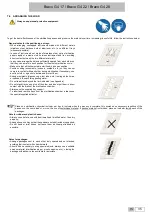
4.6.  DIRECT CONNECTION TO A CENTRALISED DRAINING POINT  

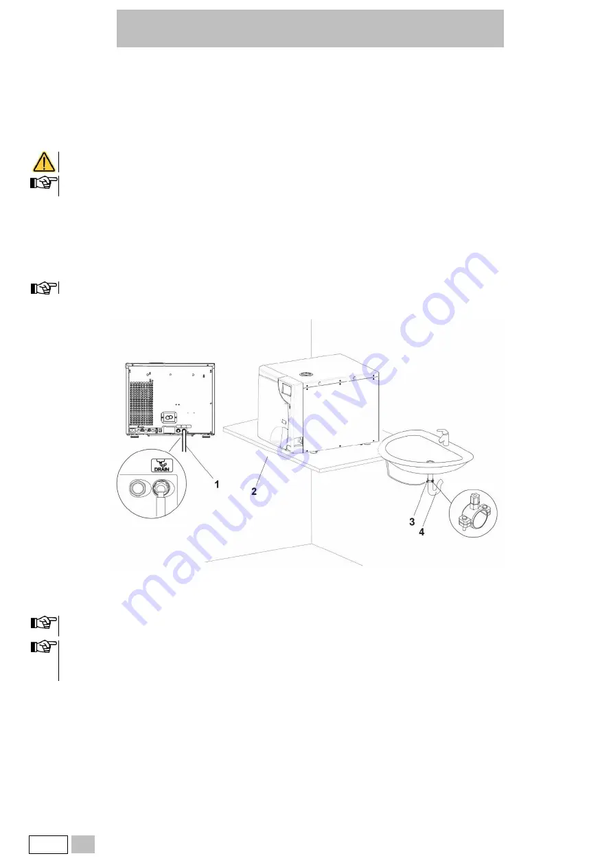
  Remove the cap holding clip and the cap on the rear of the autoclave; 

  Fit the plastic tube on the elbow union (supplied); 

  Fit the union and then refit the clip; 

  Fasten the clamp (supplied) to the drain siphon; 

  Cut the tube to the right length and insert its free end into the centralised draining point union locking it with the dedicated ring nut. 


Make sure that the tube is not bent, crushed or obstructed in any way. 


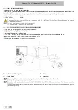
The following diagram provides an arrangement of the components: 


At the centralised draining point; 

Clamp; 

Resting surface; 

Drain siphon; 


The position of the union of the centralised draining point must be lower than the resting surface of the steriliser. 
Otherwise, the tank may not be emptied correctly. 


If an automatic filling system (external pump or H

2

O AUX EV kit (AUX SV), Pure 100, Pure 500) is connected the use of the direct drain connection 

is required. 
In case of fault or failure, this system allows any excess water produced by the automatic filling system to flow into the centralised draining point, 
thus preventing flooding. 


Summary of Contents for BRAVO G4 17

Page 1: ...BRAVO G4 Chamber Autoclave SD 601 EU ML R1 97055159 Rev 2 BRAVO is a trademark of SciCan Ltd A Coltene Group company Operator s Manual...

Page 2: ...Ltd A Coltene Group Company 1440 Don Mills Rd Toronto ON Canada M3B 3P9 T 1 416 445 1600 TF 1 800 667 7733 customerservice scican com Manufactured by CEFLA s c Headquarter Via Selice Provinciale 23 A...

Page 3: ...IN INSTALLATION 21 4 3 GENERAL PRECAUTIONS FOR INSTALLATION 21 4 4 POWER SUPPLY 21 4 5 ELECTRICAL CONNECTIONS 22 4 6 DIRECT CONNECTION TO A CENTRALISED DRAINING POINT 22 5 FIRST START UP 23 5 1 STARTI...

Page 4: ...NING 70 14 3 2 STERILISATION CHAMBER AND ACCESSORIES CLEANING 70 14 3 3 EXTERNAL SURFACE CLEANING 70 14 3 4 CHAMBER FILTER CLEANING 70 14 3 5 DOOR LOCK LUBRICATION 70 14 3 6 ANTI DUST FILTER CLEANING...

Page 5: ...t potential damage to materials devices and or property 1 2 SYMBOLS ON THE DEVICE Potential danger due to high temperature Disposal symbol in accordance with Directive 2012 19 EU Device in compliance...

Page 6: ...manufacturer will not be held responsible for any breakage malfunction property damage or injury to people in the event that the product is not installed or used correctly or proper maintenance is not...

Page 7: ...Immediately separate the materials to be sterilised from those that must not be subjected to such process or are not able to withstand it Contamination due to unsterilised material caused by wrong fi...

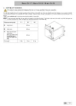
Page 8: ...ned check that The supply matches the specifications of the order see the delivery note There is no visible damage to the product Dimensions and weight A Height 600 mm B Width 600 mm C Depth 700 mm To...

Page 9: ...mentation and safety valve s EC Declaration of Conformity 10 Grey plastic tube for direct drainage with fastening clamp gasket straight fitting 4 Lubricant for door locking mechanism 11 Rear spacers 5...

Page 10: ...dled if possible using a truck or similar We recommend to transport and store the device at a temperature not below 5 C Extended exposure to low temperatures may damage the product Store the original...

Page 11: ...ability of thermodynamic parameters Moreover its Process Evaluation System constantly monitors all the machine s vital parameters in real time guaranteeing absolute safety and a perfect result The dev...

Page 12: ...ox 48 kg approx 49 kg approx 50 kg unladen with tray holder support and trays approx 51 kg approx 52 kg approx 53 kg unladen with tray holder support trays and water at MAX level approx 53 kg approx 5...

Page 13: ...gth 29 m Wi Fi 802 11 b g n 2 4 Ghz WEP WPA WPA2 PSK encryption Bacteriological filter filter element in PTFE Porosity 0 027 microns Connection male connector 1 8 NPT Maximum flow of drained water 1 l...

Page 14: ...container under pressure Action cut off of the electricity to the chamber heating element Door position safety microswitch Confirmation of the correct closing position of the door of the container un...

Page 15: ...l CONDUCTIVITY AT 20 C 15 S cm 3 S cm pH VALUE 5 7 5 7 ASPECT colourless transparent without sediment colourless transparent without sediment HARDNESS 0 02 mmol l 0 02 mmol l When buying demineralised...

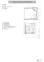
Page 16: ...screen 3 Door 4 Power switch 5 Dust filter 1 Sterilisation chamber 2 Bacteriological filter 3 Door locking system 4 Water drainage filter 5 Front filling quick connector 6 Clean water reservoir drain...

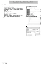
Page 17: ...distilled water filling only for PURE 100 500 H2O AUX EV kit AUX SV and automatic filling accessory kit 5 Data plate SERIAL NUMBER LABEL See image 6 Ethernet cable connection max length 29 m 7 Serial...

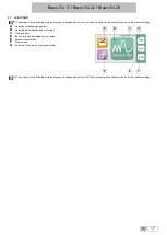
Page 18: ...steriliser display A Selection for data management B Selection of sterilisation and test cycles C Time and date D Button for quick download of new cycles E System info selection F Door unlock G Select...

Page 19: ...or sterilisation in the example 134 C 4 Pressure and temperature stabilisation 5 Load sterilisation for the required time in the example 4 minutes 6 Sterilisation chamber depressurisation 7 Vacuum dry...

Page 20: ...property damage not to mention malfunctions and damage to the device Please follow meticulously the instructions contained hereafter in this chapter Technical service department see appendix is avail...

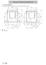
Page 21: ...Bravo G4 17 Bravo G4 22 Bravo G4 28 20 EN 4 1 OVERALL DIMENSIONS Centre distance and maximum overall dimensions of the steriliser feet with and without rear spacers A Feet B Rear spacers...

Page 22: ...ete technical data 4 3 GENERAL PRECAUTIONS FOR INSTALLATION To ensure a correct operation of the device and or avoid risky situations respect the following warnings Install the steriliser on a flat an...

Page 23: ...olding clip and the cap on the rear of the autoclave Fit the plastic tube on the elbow union supplied Fit the union and then refit the clip Fasten the clamp supplied to the drain siphon Cut the tube t...

Page 24: ...e of the machine Do not turn on the steriliser if USB key is inserted When the device is first turned on the display shows the selection of LANGUAGE DATE and TIME settings Once LANGUAGE DATE and TIME...

Page 25: ...RAVO G4 s WiFi enabled G4 technology allows connection and access to cycle data from any computer or smart device with browser capabilities allowing staff to focus on the most important thing in a den...

Page 26: ...ES 2 mg l 0 1 mg l PHOSPHATES 0 5 mg l 0 1 mg l CONDUCTIVITY AT 20 C 15 S cm 3 S cm pH VALUE 5 7 5 7 ASPECT colourless transparent without sediment colourless transparent without sediment HARDNESS 0 0...

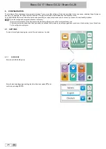
Page 27: ...arious device functions by means of a user friendly interface Use the configuration program whenever necessary A correct customisation of the device provides the best performance and the most satisfac...

Page 28: ...f the relative test Select the REMINDER option Select if and when the Test reminders Vacuum Helix B D Vacuum Helix B D should be enabled using the available options Once the fields have been set confi...

Page 29: ...ed the PIN you can access the reserved administrator menu The ADMIN user can decide whether the steriliser will ask for the generic user PIN at the cycle start PIN Start and or at the end of the cycle...

Page 30: ...mary of their data or change their PIN see entering PIN the following is requested in sequence current PIN new PIN new PIN confirmation Accessing the USERS list and selecting a generic user The ADMIN...

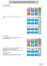
Page 31: ...Bravo G4 17 Bravo G4 22 Bravo G4 28 30 EN 6 1 5 PREFERENCES Press PREFERENCES button to enter the menu and set UNITS OF MEASUREMENT DISPLAY WATER FILLING PREHEATING...

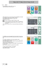
Page 32: ...ent temperature pressure the time 12 or 24 hours and the date format using the cursors shown in the figure Press ENTER to confirm the settings 6 1 5 2 DISPLAY Press the DISPLAY icon to select the scre...

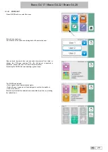
Page 33: ...etting is set to manual When you plug one of the external automatic water filling devices into the rear port the LCD will display automatically the water filling option screen so you can select the ap...

Page 34: ...ER The arrows allow setting the maximum operating time after which the warming is disabled The preheating menu is displayed when the steriliser is started for the first time after selecting the langua...

Page 35: ...al parts of the ultrasonic device Follow instrument IFU for effective cleaning 2 After washing carefully rinse the instruments and make sure that residues have been completely eliminated if necessary...

Page 36: ...sses cups test tubes etc resting on their side or upended thus avoiding pooling water Do not load trays beyond the limit indicated see Appendix Do not stack trays one on top of the other and do not pu...

Page 37: ...at right angles with tray Never stack bags one on top of the other Always pack instruments if they are going to be stored Refer also to the indications given in chapter sterilised material storage Pr...

Page 38: ...ITIONING AND USE OF TRAY HOLDER SUPPORT Tray holder support can be used in tray version 5 6 compartments based on the steriliser model It can be used to house special cassettes 3 4 compartments based...

Page 39: ...e cycle the program is immediately interrupted generating an alarm identified by a code with a relative message explaining the nature of the problem With this type of control when you select a suitabl...

Page 40: ...g button Set the minutes of drying you want to add to the standard drying time and confirm with ENTER The selected value appears near the key Activate the cycle At next use just press the extra drying...

Page 41: ...he following button Set the time you want to start the cycle selected and confirm with ENTER The selected time appears near the button Press the START button the cycle will automatically start at the...

Page 42: ...SE SECOND PRESSURE RISE THIRD VACUUM PHASE THIRD PRESSURE RISE STERILISATION STEAM DISCHARGE DRYING VENTILATION CYCLE COMPLETION 8 4 CYCLE OUTCOME At the end of the cycle it is important to check the...

Page 43: ...d down the following button to access settings Select the type of pre vacuum fractionated or single the process temperature the exposure time and total drying time Once you have made the selections us...

Page 44: ...material using dry clean and disinfected containers The containers must be closed or if open covered with clean cloths Before use sterile material must be stored using the appropriate techniques Thes...

Page 45: ...the water quality H2O TEST 10 1 HELIX B D TEST CYCLE Helix B D Test is a cycle run at 134 C characterised by a sterilisation phase that lasts a specific time 3 5 minutes the cycle comprises the fract...

Page 46: ...there will only be a partial colour change or even no change at all The same cycle can be used for the Bowie Dick test at the same time by placing the test device next to the HELIX test device Toning...

Page 47: ...tart the cycle The program will execute the two cycles in succession Check the results as described in the previous paragraphs The presence of the Helix test device and or of the Bowie Dick test devic...

Page 48: ...Bravo G4 17 Bravo G4 22 Bravo G4 28 EN 47 10 5 DOOR OPENING To open the autoclave door press and hold the button shown in the figure The door opens and stays ajar Now you can manually open the door...

Page 49: ...ror since the cycle could not finish correctly Press ENTER to proceed If the cycle is interrupted during certain phases an automatic cleaning procedure of the internal hydraulic circuit starts For the...

Page 50: ...he steriliser place the free end of the drain tube provided in the basin 2 Insert the other end of the tube in the female union beneath the chamber inlet connector on the left pushing down until you h...

Page 51: ...Bravo G4 17 Bravo G4 22 Bravo G4 28 50 EN 12 DATA MANAGEMENT To access DATA MANAGEMENT section press the relevant icon...

Page 52: ...lisation test cycle report files are in PDF format It is possible to select the number of cycles to download on the external storage device New Last 10 Last 50 Last 100 Custom Mode If Custom Mode opti...

Page 53: ...4 22 Bravo G4 28 52 EN 12 1 1 DIRECT DOWNLOAD This control performs the download of the NEW cycle reports as PDF file by means of a USB memory As NEW indicates the cycle reports have not previously be...

Page 54: ...53 12 2 WIFI Select Wi Fi to connect the steriliser to a local Wi Fi network Select ON OFF to enable or disable Wi Fi connection Select SETTINGS button to configure the network Choose NET SELECTION t...

Page 55: ...printing an extended version of the cycle summary report at the end of the process BARCODE LABELS allows printing the labels bearing the cycle data and the barcode At the end of the cycle press DOOR...

Page 56: ...vice Department for retrieving Remote Access Code The G4 Cloud web portal provides real time cycle information and archived sterilisation records unique to this unit From here you can print reports se...

Page 57: ...Medication materials gauze pads etc Other generic material suitable for autoclave treatment Depending on the material solid hollow or porous on any package containing it paper plastic bag paper for s...

Page 58: ...s in single pack 3 00 1 00 0 50 Unwrapped solid and hollow materials 6 00 1 20 0 25 Solid and hollow instruments in double pack 1 50 0 50 0 25 134 C PRION 134 2 1 18 B F 13 56 600 0 85 Unwrapped porou...

Page 59: ...g on the settings made HELIX BD TEST 134 2 1 3 5 F 1 20 Test device only without another load VACUUM TEST 0 8 18 Empty chamber VACUUM HELIX BD TEST executable in sequence 42 To set a sterilisation tim...

Page 60: ...ls in single pack 4 00 1 25 0 50 Unwrapped solid and hollow materials 7 50 1 20 0 25 Solid and hollow instruments in double pack 2 00 0 60 0 25 134 C PRION 134 2 1 18 B F 15 60 750 0 9 Unwrapped porou...

Page 61: ...g on the settings made HELIX BD TEST 134 2 1 3 5 F 1 24 Test device only without another load VACUUM TEST 0 8 18 Empty chamber VACUUM HELIX BD TEST executable in sequence 46 To set a sterilisation tim...

Page 62: ...als in single pack 5 00 1 50 0 75 Unwrapped solid and hollow materials 9 00 1 40 0 25 Solid and hollow instruments in double pack 2 50 0 70 0 25 134 C PRION 134 2 1 18 B F 17 70 950 1 Unwrapped porous...

Page 63: ...g on the settings made HELIX BD TEST 134 2 1 3 5 F 1 24 Test device only without another load VACUUM TEST 0 8 18 Empty chamber VACUUM HELIX BD TEST executable in sequence 46 To set a sterilisation tim...

Page 64: ...0 79 t2 1PP 0 97 1 03 t3 2PV 0 81 0 79 t4 2PP 0 97 1 03 t5 3PV 0 81 0 79 t6 SS 4 5 5 134 137 2 04 2 31 t7 SE 4 5 5 134 137 2 04 2 31 t8 DS 0 81 0 79 t9 DE 2 CE 0 02 0 02 121 C cycles EN 13060 2014 A1...

Page 65: ...M DIAGRAM PROGRAM 134 C UNIVERSAL 134 C 4 00 5 30 PROGRAM 134 C PRION 134 C 18 00 A PRESSURE BAR B PROCESS C TIME MIN D FRACTIONATED VACUUM E VACUUM DRYING PROGRAM 121 C UNIVERSAL 121 C 20 00 A PRESSU...

Page 66: ...EN 65 PROGRAM 134 C HOLLOW UNWRAPPED 134 C 4 00 A PRESSURE BAR B PROCESS C TIME MIN F FRACTIONATED PRE VACUUM H SHORT DRYING PROGRAM 134 C SOLID WRAPPED 134 C 4 00 A PRESSURE BAR B PROCESS C TIME MIN...

Page 67: ...AM HELIX B D TEST 134 C 3 0 A PRESSURE BAR B PROCESS C TIME MIN F FRACTIONATED PRE VACUUM H SHORT DRYING PROGRAM VACUUM TEST 0 80 bar A PRESSURE BAR C TIME MIN L INTERMEDIATE CONDITION TO CONTINUE THE...

Page 68: ...PROGRAM PRINTING STANDARD PROGRAM PRINTING HELIX B D TEST PROGRAM PRINTING VACUUM TEST The text printed on the receipt remains for a couple of years if correctly stored away from any source of heat a...

Page 69: ...order In case of heavy use we recommend to shorten maintenance intervals DAILY Clean the door gasket and the internal part of the door 14 3 1 Clean the chamber drain filter 14 3 4 WEEKLY Clean extern...

Page 70: ...materials or products for metal cleaning both solid and liquid to clean the device or the sterilisation chamber Do not use unsuitable chemical products or disinfectants to clean the sterilisation cha...

Page 71: ...ted with water Apply product with a soaked cloth then dry Do not spray or vaporise any product directly on device surfaces Inflammable liquid 14 3 4 CHAMBER FILTER CLEANING With use it is likely that...

Page 72: ...When filter maintenance is due or every time you notice visible clogging of the filter indicated by the filter markedly turning grey unscrew the bacteriological filter B from its support and replace i...

Page 73: ...ent see Appendix is available to provide any information relative to the periodic validation of steam sterilisers 14 5 DEVICE USEFUL LIFE Steam steriliser service life is of 10 years average use 5 cyc...

Page 74: ...ut 10 15 Minutes The safety valve has triggered Locking ring loosened Presence of anomalous overpressure in the chamber Contact Technical Service Water presence on the steriliser resting surface The w...

Page 75: ...paring the material Presence of limescale residues on the wall of the chamber and or accessories Clean the chamber and the accessories as prescribed See Appendix Maintenance Blackening of the instrume...

Page 76: ...R Electronic system error HW FW Code format Sxxx xxx identification number 000 999 In case of alarm switch off the device only after having followed the indications displayed and having carried out th...

Page 77: ...OOR 1 E011 Water conductivity threshold 2 exceeded by filling tank QUALITY H2O BAD CHANGE WATER 2 E020 Door lock system closing activation time out exceeded DOOR CLOSING ERROR CONTACT TECH SERVICE 1 t...

Page 78: ...EASE UPDATE THIS FW 1 E900 Vacuum test failed during TEST PHASE TEST FAILED SECOND STEP CONTACT TECH SERVICE 2 E901 Vacuum test failed during STAND BY PHASE TEST FAILED FIRST STEP CONTACT TECH SERVICE...

Page 79: ...emperature sensor PT2 short circuited steam generator GENERATOR PROBE PT2 SHORT CIRCUIT CONTACT TECH SERVICE 1 A113 Temperature sensor PT3 short circuited heating element HEATING BAND PROBE PT3 SHORT...

Page 80: ...MEOUT CONTACT TECH SERVICE 2 A255 2nd pressure pulse not reached within the time out 2PP UPSTROKE TIMEOUT CONTACT TECH SERVICE 2 A256 3rd pulse with vacuum not achieved within time out 3PV TIMEOUT CHE...

Page 81: ...SATION phase TEMPERATURE BELOW MINIMUM LIMIT CONTACT TECH SERVICE 2 H404 Floating temperature over the limit STERILISATION phase ERRATIC TEMPERATURE CONTACT TECH SERVICE 2 H405 Pressure over the MAX l...

Page 82: ...p not done RUN BACKUP DOWNLOAD NEW CYCLES 2 S021 Cycle storage limit exceeded CYCLE MEMORY FULL START OVERWRITING 2 S030 Check using a watchdog that one of main tasks is not in crash condition SYSTEM...

Page 83: ...chnician E007 One or more rear fans failed RESET according to the instructions Check the operation of rear fans and contact Technical Service see Appendix E008 The filling discharge tank contains wate...

Page 84: ...isappear and restart the machine E141 The cloud firmware version is not the correct one with respect to the firmware process There may be malfunctions in the connection with WiFi ethernet or cloud Con...

Page 85: ...ent compensation A111 Incorrect temperature sensor connection sterilisation chamber Temperature sensor short circuit sterilisation chamber A112 Incorrect temperature sensor connection steam generator...

Page 86: ...t insert material impregnated with water or in general with liquids into the chamber Air seepage through the gasket RESET according to the instructions Thoroughly clean the gasket with a clean cotton...

Page 87: ...ndix A261 Bacteriological filter obstructed Clean the drain filter see Maintenance Appendix Problem in the hydraulic circuit Contact Technical Service see Appendix A262 Bacteriological filter obstruct...

Page 88: ...it H401 Problem in the hydraulic circuit H402 Steam generator malfunction Problem in the hydraulic circuit H403 Steam generator malfunction Problem in the hydraulic circuit H404 Problem in the hydraul...

Page 89: ...correctly loaded Check printer cable correct connection Make sure that paper settings are correct If the problem persists contact Technical Service see Appendix S020 Cycle back up not done after 250 c...

Page 90: ...ts and accessories that meet the manufacturer s specifications DEMINERALISER PURE 100 DEMINERALISER PURE 500 AUTOMATIC FILLING KIT FRONT FILLING KIT H2O AUX EV kit AUX SV Auxiliary solenoid valve kit...

Page 91: ...r loaded see the paragraph PRINT MANAGEMENT Refer to the printer manual for printer starting and paper loading 21 APPENDIX SPARE PARTS AND ACCESSORIES Only use spare parts and accessories that meet th...

Page 92: ...ocedures In this regard please refer to the following address Head Office SciCan Ltd 1440 Don Mills Rd Toronto ON Canada M3B 3P9 T 1 416 445 1600 TF 1 800 667 7733 customerservice scican com www scica...

Reviews:

Related manuals for BRAVO G4 17