background image


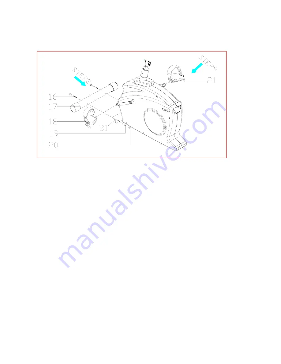
Attach Front Stabilizer Tube and Pedals to Main Unit 


Assembly Hardware Required: 


) M8 Bolt 75mm long (item #16) 

      (2) 

Curved 

Washers 

(item 

#19) 

Acorn 

Nut 

(item 

#20) 

Step 8: 

Attach FRONT STABILIZER TUBE (#17) to the MAIN UNIT (#31) with 

the M8 BOLT 75mm (#16), CURVED WASHER (#19), and ACORN NUT (#20).  
Tighten Bolts with provided wrench. 
 

Step 9: 

Attach RIGHT PEDAL (#21) to the right crank arm on the MAIN UNIT 

read 

L.  The threading on the left pedal 

ing of the threads be 

areful to use the proper pedal. 


Assembly Stage #3 


(2

      (2) 
 

(#31).  Thread the pedal onto the crank arm and then tighten with pedal wrench. 
Attach LEFT PEDAL (#21) to the left crank arm on the MAIN UNIT (#31).  Th
the pedal onto the crank arm and then tighten with pedal wrench.  

Note: There is a 

right pedal and a left pedal, marked by R and 
is reversed from the right pedal.  Counterclockwise rotation tightens while 
Clockwise rotation loosens on the left pedal.  To avoid stripp
c

Attach PEDAL STRAPS (#18) to each PEDAL (#21).  Again, each strap is labeled 
with an R or an L corresponding to the right and left pedal straps.


Summary of Contents for 202 Recumbent Bike

Page 1: ...202 Schwinn Recumbent Exercise Bike Parts List Full Size Hardware Chart Product Illustration Assembly Instructions 202 Recumbent Exercise Bike...

Page 2: ...ften Replace any worn parts immediately 6 Keep small children and pets away from this equipment at all times 7 Always wear athletic shoes for foot protection Do not wear loose or dangling clothing whi...

Page 3: ...a of 5 x 7 is suggested to assemble the 202 exercise bike You will need the following tools to complete the assembly 5mm Allen wrench supplied Open wrench 13mm 14mm 15mm supplied Phillips screwdriver...

Page 4: ...lt M8 x P1 25 x 75mm 16 __ 1 Front Stabilizer Tube w wheels 17 __ 1pr Pedal Strap Left Right 18 __ 8 Curved Washer 19 __ 4 Acorn Nut 20 __ 1pr Pedals Left Right 21 __ 19 Allen Bolt M8 x P1 25 x 16mm 2...

Page 5: ...mponents please call 1 800 4 MY HOME for assistance Flat Washer for 8 16 2T Flat Washer 8 19 2T Allen Bolt M8xP1 25x16mm Flat Washer 8 19 2T Flat Washer Carriage Bolt M8xP1 25x75mm Curved Washer Stage...

Page 6: ...202 Assembly Drawing with Reference Numbers 30 2 22 23 22 20 19 32 31 20 19 18 16 17 28 21 22 26 19 25 29 27 11 24 10 22 2 8 47 9 56 57 33 34 58 3 15 14 13 12...

Page 7: ...Carriage Bolt M8 x P1 25 x 75mm 17 Front Stabilizer Tube w wheels 20 Acorn Nut 21 Pedals Left Right 22 Allen Bolt M8 x P1 25 x 16mm 23 Bolt Cover 24 Carriage Bolt M8 x P1 25 x 90mm 25 Computer Cable...

Page 8: ...ly hardware required 8 M8 Allen Bolts 45 mm long item 1 8 Flat Washers 8 19 2T item 2 4 M8 Allen Bolts 16 mm long item 22 4 Flat Washer 8 16 2T item 7 Step 1 Attach HANDLEBAR ASSEMBLY 6 to SEAT FRAME...

Page 9: ...TS Step 3 Attach SEAT BAC with 4 ALLEN BOL 1 and 4 WASHERS 2 Tighten Bolts Note Finished seat should look like picture below K 5 to SEAT FRAME 8...

Page 10: ...strung through the exit slot on the SEAT RAIL before end cap is secured Step 6 Insert SEAT PIN ADJUSTMENT KNOB 3 into SEAT FRAME 8 Slide the seat assembly from stage 1 onto the SEAT RAIL 9 Tighten sea...

Page 11: ...ing of the threads be areful to use the proper pedal Assembly Stage 3 2 2 31 Thread the pedal onto the crank arm and then tighten with pedal wrench Attach LEFT PEDAL 21 to the left crank arm on the MA...

Page 12: ...ired 7 Allen Bolts 16 mm long item 3 Flat Washers item 2 2 Allen Bolts 90 mm long item 24 2 Curved Washers item 19 4 Flat Washer item 7 Ste wit n unt 31 p 10 Slide the LOWER BASE FRAME 32 into the MAI...

Page 13: ...ottom of the seat rail it may be severed or damaged when the seat rail is fully inserted into the main unit This may result in a non functioning handgrip heart rate Carefully slide the seat rail until...

Page 14: ...ily omplete this step it would be helpful to have someone hold the CONSOLE MAST 30 nd CONSOLE MAST COVER 27 while connecting the cables Fasten with 4 OLTS 22 and 4 CURVED WASHERS 19 Tighten with provi...

Page 15: ...ER TUBE 17 Seat Adjustment For best results the seat should be adjusted for your height 1 Unlock seat locking mechanism 2 Adjust seat location so that with feet on the pedals you can comfortably reach...

Page 16: ...ance ROBLEM Bike will not sit level OLUTION 1 Adjust the levelers on the rear stabilizer Exercise Bike IP Use assembly diagram s as reference when troubleshooting unit T PROBLEM Computer will not star...

Page 17: ......

Reviews: