


2.9
Date Code 20081022
Instruction Manual
SEL-787 Relay
Installation
I/O Configuration
Step 8. Press the
{Down Arrow}
pushbutton until
STATUS
is highlighted.
Step 9. Press the
{ENT}
pushbutton.
The front-panel displays the following:
Confirm Hardware
Config (Enter)
Step 10. Press the
{ENT}
pushbutton.
The front-panel displays the following:
Accept Config?
Yes No
Step 11. Select
Yes
and press the
{ENT}
pushbutton.
The front-panel displays the following:
Config Accepted
Enter to Restart
Step 12. Press
{ENT}
.
The relay restarts and the
ENABLED
light is turned on to indicate
the option card was installed correctly.
After reconfiguration, the relay updates the part number, except
for the digits shown below. These digits remain unchanged, i.e.,
these digits retain the same character as before the
reconfiguration. Also, a communications card installed in
Slot
C
will be reflected as an empty slot in the part number. Use
the
STATUS
command to view the part number.
Step 13. Attach the terminal marking label (provided with the card) to
the rear cover so that the
INTERFACE CARD EXPANSION SLOT
is
covered.
Step 14. Reconnect all connection plugs, and add any additional wiring/
connectors required by the new option card. Use the new rear-
panel if it is supplied with the card.
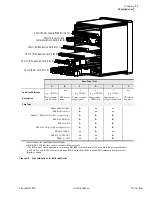
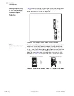
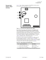
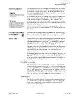
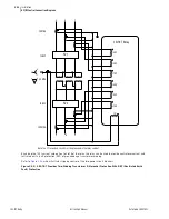
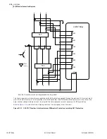
Analog Input (4 AI/
4 AO Card) Voltage/
Current Jumper
Selection
shows the circuit board of an analog I/O board. Jumper
x
(
x
= 5–8)
determines the nature of each channel. For a current channel, insert Jumper
x
in position 1–2; for a voltage channel, insert Jumper
x
in position 2–3.
Figure 2.3
Circuit Board of Analog I/O Board, Showing Jumper Selection
PART NUM =
0 7 8 7 0 X 1 A 6 X 3 A 1 A 8 5 0 2 0 X
JMPX
2
1
3
JMPX
2
1
3
Position 2 – 3 = V (voltage) mode
Where "JMPX" is the jumper for AI channel "X"
Position 1 – 2 = I (current) mode
Summary of Contents for SEL-787
Page 1: ...20081022 SEL 787 Transformer Protection Relay Instruction Manual PM787 01 NB ...
Page 6: ...This page intentionally left blank ...
Page 12: ...This page intentionally left blank ...
Page 18: ...This page intentionally left blank ...
Page 78: ...This page intentionally left blank ...
Page 206: ...This page intentionally left blank ...
Page 280: ...This page intentionally left blank ...
Page 334: ...This page intentionally left blank ...
Page 376: ...This page intentionally left blank ...
Page 388: ...This page intentionally left blank ...
Page 474: ...This page intentionally left blank ...
Page 508: ...This page intentionally left blank ...