

4.79
Date Code 20081022
Instruction Manual
SEL-787 Relay
Protection and Logic Functions
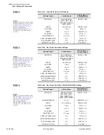
Logic Settings (SET L Command)
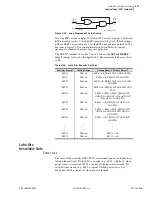
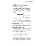
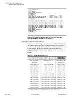
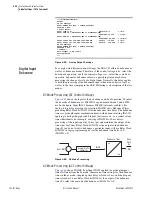
The pickup times of 0 for the SV03PU and SV04PU settings shown above
provide an immediate Close and Trip actions from front-panel pushbuttons.
For a delayed Close, set SV03PU to the desired delay. Similarly, set SV04PU
for a delayed Trip action. See
for more detail.
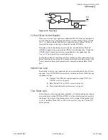
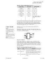
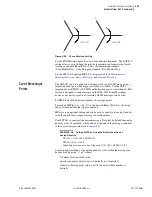
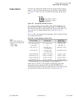
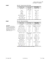
Counter Variables
SEL
OGIC
counters are up- or down-counting elements, updated every
processing interval.
Each counter element consists of one count setting, four control inputs, two
digital outputs, and one analog output.
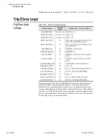
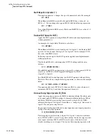
shows Counter 01, the first
of 32 counters available in the device.
Figure 4.51
Counter 01
Digital output SC01QD asserts when the counter is at position zero, and
Digital output SC01QU asserts when the counter reaches the programmable
count value. Use the reset input (SC01R) to force the count to zero, and the
analog output (SC
nn
) with analog comparison operators.
describes
the counter inputs and outputs, and
shows the order of precedence
of the control inputs.
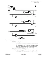
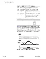
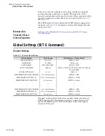
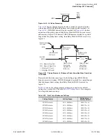
SV TIMER DROPOUT
0.00–3000.00 sec
SV03DO := 0.00
SV INPUT
SEL
OGIC
SV03 := LT03
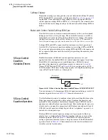
SV TIMER PICKUP
0.00–3000.00 sec
SV04PU := 0.00
SV TIMER DROPOUT
0.00–3000.00 sec
SV04DO := 0.00
SV INPUT
SEL
OGIC
SV04 := LT04
SV TIMER PICKUP
0.00–3000.00 sec
SV05PU := 0.25
SV TIMER DROPOUT
0.00–3000.00 sec
SV05DO := 0.25
SV INPUT
SEL
OGIC
SV05 := (PB01 OR PB02 OR
LT03 OR LT04) AND NOT
SV05T
•
•
•
•
•
•
•
•
•
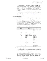
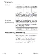
Table 4.29
SEL
OGIC
Variable Settings
(Sheet 2 of 2)
Setting Prompt
Setting Range
Default Settings
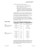
Table 4.30
Counter Input/Output Description
(Sheet 1 of 2)
Name
Type
Description
SC
nn
LD
Active High Input
Load counter with the preset value to assert the output
(SC
n
QU) (follows SEL
OGIC
setting).
SC
nn
PV
Input Value
This Preset Value is loaded when SC
n
LD pulsed. This
Preset Value is the number of counts before the output
(SC
n
QU) asserts (follows SEL
OGIC
setting).
SC
nn
CU
Rising-Edge Input
Count Up increments the counter (follows SEL
OGIC
setting).
NOTE:
These counter elements
conform to the standard counter
function block #3 in IEC 1131-3 First
Edition 1993-03 International
Standard for Programmable
controllers—Part 3: Programming
languages.
NOTE:
For device configurations that
include voltage cards, the SEL-787
tracks the frequency. When tracking
the frequency, the processing interval
varies with the frequency.
NOTE:
If setting SCnnCD is set to NA,
the entire counter nn is disabled).
SC01PV
SC01R
SC01LD
SC01CU
SC01CD
Counter 01
SC01QU
SC01QD
SC01
SEL
OGIC
Output
Summary of Contents for SEL-787
Page 1: ...20081022 SEL 787 Transformer Protection Relay Instruction Manual PM787 01 NB ...
Page 6: ...This page intentionally left blank ...
Page 12: ...This page intentionally left blank ...
Page 18: ...This page intentionally left blank ...
Page 78: ...This page intentionally left blank ...
Page 206: ...This page intentionally left blank ...
Page 280: ...This page intentionally left blank ...
Page 334: ...This page intentionally left blank ...
Page 376: ...This page intentionally left blank ...
Page 388: ...This page intentionally left blank ...
Page 474: ...This page intentionally left blank ...
Page 508: ...This page intentionally left blank ...