

4.74
SEL-787 Relay
Instruction Manual
Date Code 20081022
Protection and Logic Functions
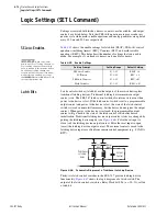
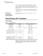
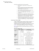
Logic Settings (SET L Command)
Settings Change
If individual settings are changed, the states of the latch bits (Relay Word bits
LT01 through LT32) are retained, as in the preceding
explanation. If the individual settings change causes a change in SEL
OGIC
control equation settings SET
n
or RST
n
(
n
= 1 through 32), the retained states
of the latch bits can be changed, subject to the newly enabled settings SET
n
or
RST
n
.
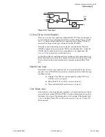
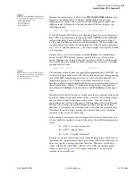
Make Latch Control Switch Settings With Care
The latch bit states are stored in nonvolatile memory so they can be retained
during power loss or settings change. The nonvolatile memory is rated for a
finite number of writes for all cumulative latch bit state changes. Exceeding
the limit can result in a flash self-test failure.
An average of 70 cumulative
latch bit state changes per day can be made for a 25-year device service life.
Settings SET
n
and RST
n
cannot result in continuous cyclical operation of
latch bit LT
n
. Use timers to qualify conditions set in settings SET
n
and RST
n
.
If you use any optoisolated inputs in settings SET
n
and RST
n
, the inputs each
have a separate debounce timer that can help in providing the necessary time
qualification.
SEL
OGIC
Control
Equation
Variables/Timers
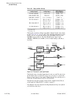
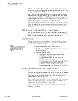
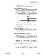
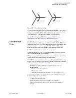
Enable the number of SEL
OGIC
control equations necessary for your
application. Only the enabled SEL
OGIC
control equations appear for settings.
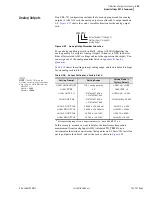
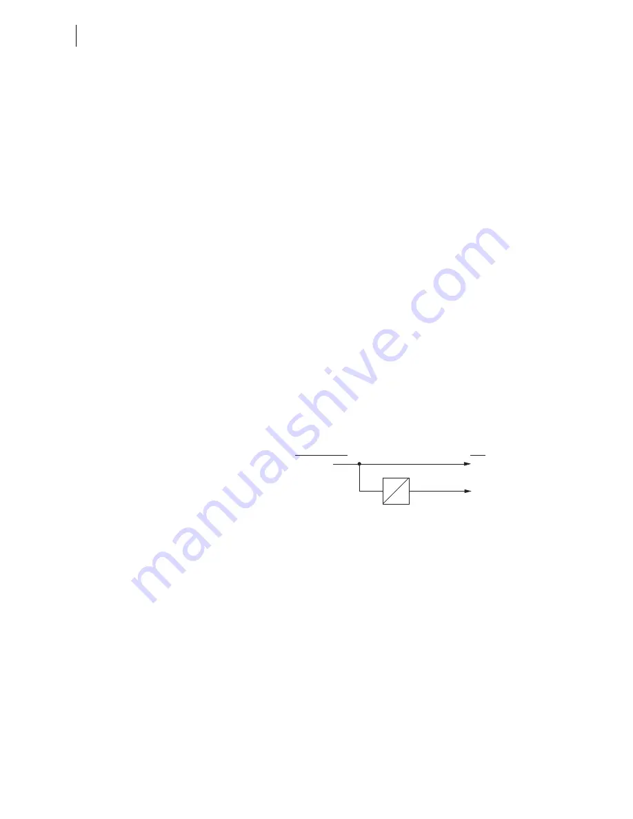
Each SEL
OGIC
control equation variable/timer has a SEL
OGIC
control
equation setting input and variable/timer outputs as shown in
.
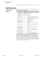
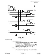
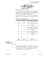
Timers SV01T through SV32T in
have a setting range of 0.00–
3000.00 seconds. This timer setting range applies to both pickup and dropout
times (SV
n
PU and SV
n
DO,
n
= 1 through 32).
Figure 4.48
SEL
OGIC
Control Equation Variable/Timers SV01/SV01T—SV32T
You can enter up to 15 elements per SEL
OGIC
equation, including a total of 14
elements in parentheses (see
for more information).
SEL
OGIC
Control
Equation Operators
Use the Boolean operators to combine values with a resulting Boolean value.
Edge trigger operators provide a pulse output. Combine the operators and
operands to form statements that evaluate complex logic. SEL
OGIC
control
equations are either Boolean type or math type. Because the equals sign (=) is
already used as an equality comparison, both Boolean type and math type of
SEL
OGIC
control equation settings begin with an “assignment” operator (:=)
instead of with an equals sign.
Boolean SEL
OGIC
control equation settings use logic similar to Boolean
algebra logic, combining Relay Word bits together with one or more of the
Boolean operators listed in
. Math SEL
OGIC
control equation
settings operate on numerical values, using one or more of the Mathematical
operators listed in
. These numerical values can be mathematical
variables or actual real numbers.
SVn
SVn
SVnT
SEL
OGIC
Variable/
Timer Input Settings
Relay
Word
Bits
SVnPU
SVnDO
Summary of Contents for SEL-787
Page 1: ...20081022 SEL 787 Transformer Protection Relay Instruction Manual PM787 01 NB ...
Page 6: ...This page intentionally left blank ...
Page 12: ...This page intentionally left blank ...
Page 18: ...This page intentionally left blank ...
Page 78: ...This page intentionally left blank ...
Page 206: ...This page intentionally left blank ...
Page 280: ...This page intentionally left blank ...
Page 334: ...This page intentionally left blank ...
Page 376: ...This page intentionally left blank ...
Page 388: ...This page intentionally left blank ...
Page 474: ...This page intentionally left blank ...
Page 508: ...This page intentionally left blank ...