


J-2
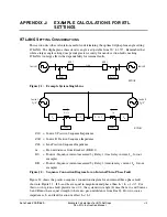
Example Calculations for 87L Settings
Date Code 20010625
SEL-311L Instruction Manual
Calculating I
AR
/I
AL
for Phase Faults
We can use positive-sequence currents from each line terminal to evaluate three-phase faults (see
Equation J.1 and Equation J.2). Equation J.3 shows the ratio of remote to local positive-
sequence currents. Note that I
1R
/ I
1L
= I
AR
/ I
AL
for balanced faults.
L
1
S
1
S
S
1
mZ
Z
E
I
+
°
δ
∠
=
Equation J.1
(
)
L
1
R
1
R
R
1
Z
•
m
1
Z
0
E
I
−
+
°
∠
=
Equation J.2
[
]
(
)
[
]
L
1
R
1
L
1
S
1
S
R
AL
AR
S
1
R
1
Z
•
m
1
Z
Z
•
m
Z
•
E
0
E
I
I
I
I
−
+
+
°
δ
∠
°
∠
=
=
Equation J.3
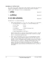
From Equation J.3, we conclude the following:
1. If the system is homogeneous (i.e.,
∠
Z
1S
=
∠
Z
1L
=
∠
Z
1R
), then
∠
(I
1R
/ I
1S
) is zero when
δ
= 0°. In our default settings, we assumed
δ
= 10°. Given the following system:
•
System Voltage:
230 kV
LL
•
Line Length:
10 miles
•
Line Impedance:
0.8
Ω
/mi (8.0
Ω
primary total)
•
Source S and R Impedance: ½ Z
LINE
•
Current Transformer Ratio: 1200/5 (240:1)
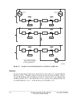
Increasing
δ
greater than 10° causes the secondary line current to exceed 6 A. In actual
practice, we expect the source impedances to be much lower. From this we conclude
that 10° is a reasonable maximum value for
δ
.
2. If the system is non-homogeneous, this too can create an angle difference between I
1R
and I
1S
. The extent of the angle difference depends in part on the fault location. For
example, if Source R and the Line have the same angle and
∠
Z
1S
is 10° less than
∠
Z
1R
, a
fault at m = 0 creates a 10° difference between the remote and local currents. Moving
the fault location to m = 1 creates a 3.3° difference between the phase currents. As a
worst case study, the non-homogeneous angle difference can add with the angle
difference caused by
δ
= 10°. If the
∠
Z
1S
is 10° greater than
∠
Z
1R
for the fault at m = 0,
the non-homogenous system angle and system load angle errors cancel: I
AR
and I
AL
are
then in-phase.
Summary of Contents for SEL-311L
Page 6: ......
Page 8: ......
Page 26: ......
Page 54: ......
Page 144: ......
Page 216: ......
Page 252: ......
Page 302: ......
Page 338: ......
Page 480: ......
Page 484: ......
Page 486: ......
Page 502: ......
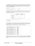
Page 532: ...12 28 Standard Event Reports and SER Date Code 20010625 SEL 311L Instruction Manual 4 ...
Page 552: ......
Page 554: ......
Page 574: ......
Page 576: ......
Page 596: ......
Page 602: ......
Page 628: ......
Page 656: ......
Page 662: ......
Page 664: ......
Page 688: ......
Page 700: ......
Page 716: ......
Page 722: ......
Page 734: ......