


7-12
Inputs, Outputs, Timers, and Other Control Logic
Date Code 20010625
SEL-311L Instruction Manual
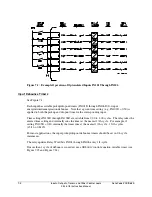
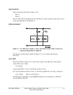
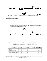
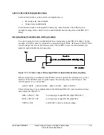
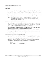
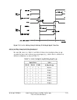
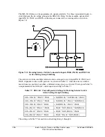
Figure 7.10: Traditional Latching Relay
The sixteen (16) latch control switches in the SEL-311L Relay provide latching relay type
functions.
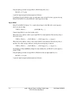
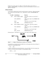
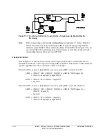
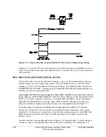
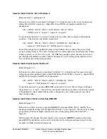
Figure 7.11: Latch Control Switches Drive Latch Bits LT1 Through LT16
The output of the latch control switch in Figure 7.11 is a Relay Word bit LT
n
(
n
= 1 through 16),
called a latch bit. The latch control switch logic in Figure 7.11 repeats for each latch bit LT1
through LT16. Use these latch bits in SEL
OGIC
control equations.
These latch control switches each have the following SEL
OGIC
control equation settings:
SET
n
(set latch bit LT
n
to logical 1)
RST
n
(reset latch bit LT
n
to logical 0)
If setting SET
n
asserts to logical 1, latch bit LT
n
asserts to logical 1. If setting RST
n
asserts to
logical 1, latch bit LT
n
deasserts to logical 0. If both settings SET
n
and RST
n
assert to logical 1,
setting RST
n
has priority and latch bit LT
n
deasserts to logical 0.
Summary of Contents for SEL-311L
Page 6: ......
Page 8: ......
Page 26: ......
Page 54: ......
Page 144: ......
Page 216: ......
Page 252: ......
Page 302: ......
Page 338: ......
Page 480: ......
Page 484: ......
Page 486: ......
Page 502: ......
Page 532: ...12 28 Standard Event Reports and SER Date Code 20010625 SEL 311L Instruction Manual 4 ...
Page 552: ......
Page 554: ......
Page 574: ......
Page 576: ......
Page 596: ......
Page 602: ......
Page 628: ......
Page 656: ......
Page 662: ......
Page 664: ......
Page 688: ......
Page 700: ......
Page 716: ......
Page 722: ......
Page 734: ......