


5-30
Trip and Target Logic
Date Code 20010625
SEL-311L Instruction Manual
D
IRECTIONAL
C
OMPARISON
B
LOCKING
(DCB) L
OGIC
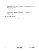
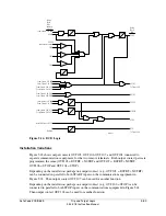
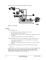
Enable the DCB logic by setting ECOMM = DCB. The DCB logic in Figure 5.16 performs the
following tasks:
v
Provides the individual carrier coordination timers for the Level 2 directional elements M2P,
Z2G, 67G2, and 67Q2 via the Z2PGS and 67QG2S Relay Word bits. These delays allow
time for the block trip signal to arrive from the remote terminal. For example:
TRCOMM = Z2PGS + 67QG2S
v
Instantaneously keys the communications equipment to transmit block trip for reverse faults
and extends this signal for a settable time following the dropout of all Level 3 directional
elements (M3P, Z3G, 67G3, and 67Q3).
v
Latches the block trip send condition by the directional overcurrent following a close-in
zero-voltage three-phase fault where the polarizing memory expires. Latch is removed when
the polarizing memory voltage returns or current is removed.
v
Extends the received block signal by a settable time.
Use Existing SEL-321 Relay DCB Application Guide for the SEL-311L Relay
Use the existing SEL-321 Relay DCB application guide (AG93-06) to help set up the SEL-311L
Relay in a DCB scheme (see preceding subsection
Communications-Assisted Trip Logic
—
General Overview
for more setting comparison information on the SEL-321/SEL-311L Relays).
External Inputs
See
Optoisolated Inputs
in
Section 7: Inputs, Outputs, Timers, and Other Control Logic
for
more information on optoisolated inputs.
BT—Received Block Trip Signal(s)
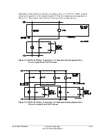
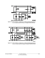
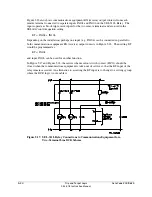
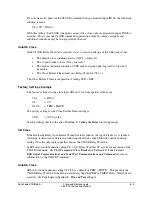
In two-terminal line DCB applications, a block trip signal is received from one remote terminal.
One optoisolated input on the SEL-311L Relay (e.g., input IN104) is driven by a
communications equipment receiver output (see Figure 5.17). Make SEL
OGIC
control equation
setting BT:
BT = IN104
(two-terminal line application)
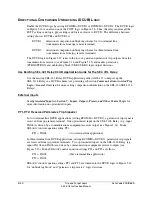
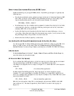
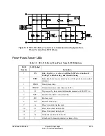
In three-terminal line DCB applications, block trip signals are received from two remote
terminals. Two optoisolated inputs on the SEL-311L Relay (e.g., input IN104 and IN106) are
driven by communications equipment receiver outputs (see Figure 5.18). Make SEL
OGIC
control
equation setting BT as follows:
BT = IN104 + IN106
(three-terminal line application)
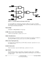
SEL
OGIC
control equation setting BT is routed through a dropout timer (BTXD) in the DCB
logic in Figure 5.16. The timer output, Relay Word bit BTX, is routed to the trip logic in
Figure 5.4.
Summary of Contents for SEL-311L
Page 6: ......
Page 8: ......
Page 26: ......
Page 54: ......
Page 144: ......
Page 216: ......
Page 252: ......
Page 302: ......
Page 338: ......
Page 480: ......
Page 484: ......
Page 486: ......
Page 502: ......
Page 532: ...12 28 Standard Event Reports and SER Date Code 20010625 SEL 311L Instruction Manual 4 ...
Page 552: ......
Page 554: ......
Page 574: ......
Page 576: ......
Page 596: ......
Page 602: ......
Page 628: ......
Page 656: ......
Page 662: ......
Page 664: ......
Page 688: ......
Page 700: ......
Page 716: ......
Page 722: ......
Page 734: ......