


7-18
Inputs, Outputs, Timers, and Other Control Logic
Date Code 20011205
SEL-311B Instruction Manual
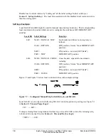
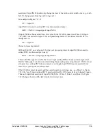
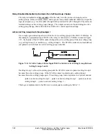
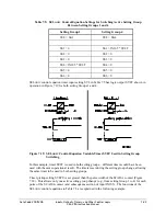
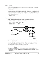
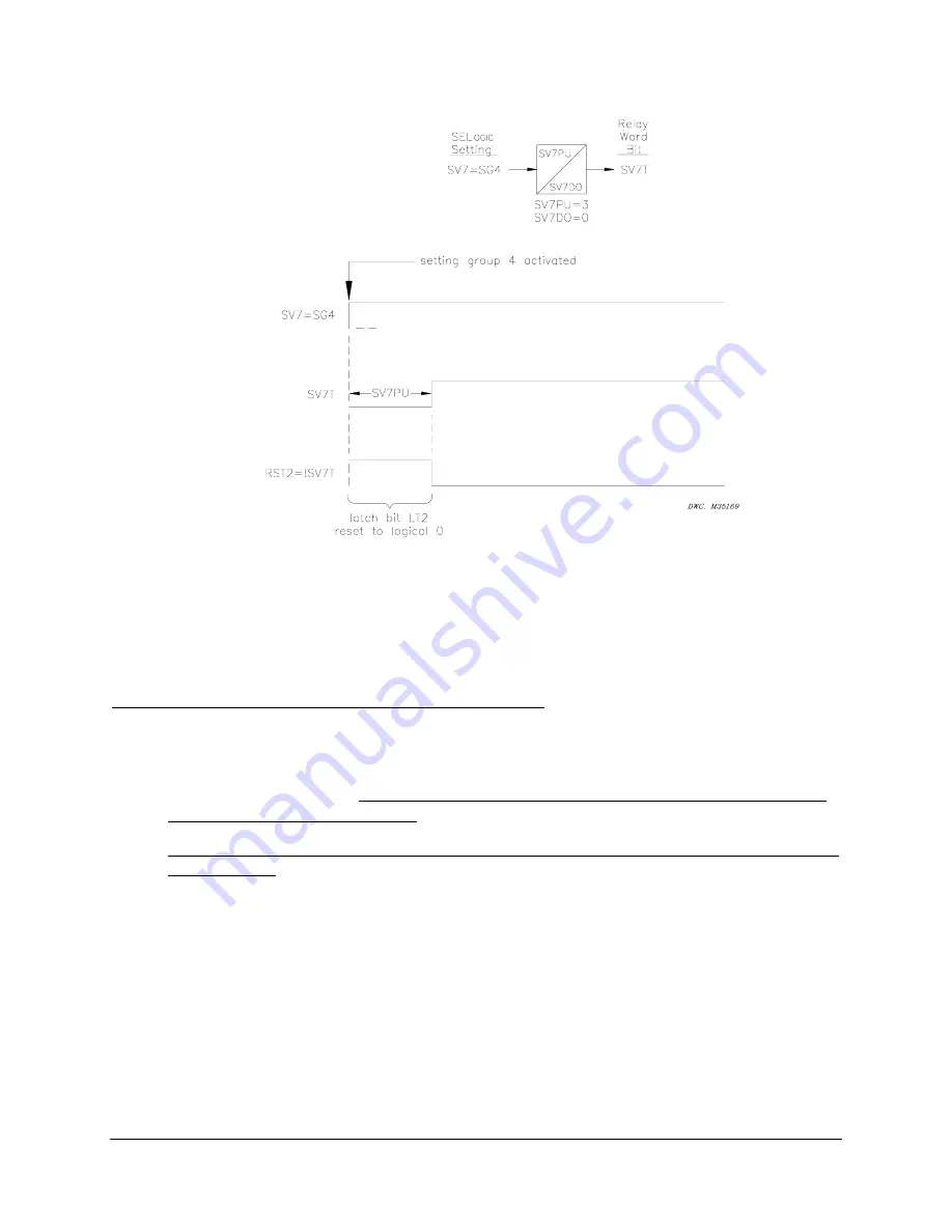
Figure 7.15: Time Line for Reset of Latch Bit LT2 After Active Setting Group Change
In Figure 7.15, latch bit LT2 is reset (deasserted to logical 0) when reset setting RST2 asserts to
logical 1 for the short time right after setting Group 4 is activated. This logic can be repeated for
other latch bits.
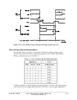
Note: Make Latch Control Switch Settings with Care
The latch bit states are stored in nonvolatile memory so they can be retained during power loss,
settings change, or active setting group change. The nonvolatile memory is rated for a finite
number of “writes” for all cumulative latch bit state changes. Exceeding the limit can result in an
EEPROM self-test failure. An average of 150 cumulative latch bit state changes per day can be
made for a 25-year relay service life.
This requires that SEL
OGIC
control equation settings SET
n
and RST
n
for any given latch bit LT
n
be set with care. Settings SET
n
and RST
n
cannot result in continuous cyclical operation of latch
bit LT
n
. Use timers to qualify conditions set in settings SET
n
and RST
n
. If any optoisolated
inputs IN101 through IN106 are used in settings SET
n
and RST
n
, the inputs have their own
debounce timer that can help in providing the necessary time qualification (see Figure 7.1).
In the preceding reclosing relay enable/disable example application (Figure 7.12 through Figure
7.14), the SCADA contact cannot be asserting/deasserting continuously, thus causing latch bit
LT1 to change state continuously. Note that the rising edge operators in the SET1 and RST1
settings keep latch bit LT1 from cyclically operating for any single assertion of the SCADA
contact.
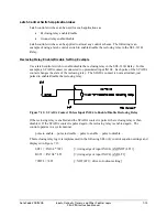
Another variation to the example application in Figure 7.12 through Figure 7.14 that adds more
security is a timer with pickup/dropout times set the same (see Figure 7.16 and Figure 7.17).
Summary of Contents for SEL-311B
Page 6: ......
Page 8: ......
Page 10: ......
Page 24: ......
Page 26: ......
Page 122: ......
Page 124: ......
Page 138: ......
Page 168: ......
Page 172: ......
Page 254: ......
Page 282: ......
Page 306: ......
Page 348: ......
Page 364: ......
Page 366: ......
Page 448: ......
Page 460: ......
Page 466: ......
Page 476: ......
Page 482: ......
Page 494: ......
Page 500: ......
Page 522: ......
Page 526: ......
Page 528: ......
Page 534: ......
Page 536: ......
Page 550: ......
Page 570: ......
Page 586: ......
Page 600: ......


