SCHUNK VERO-S NSE mini 90-25 Assembly And Operating Manual Download Page 41


Appendix on Declaration of Incorporation, as per 2006/42/EC, 

annex II, No. 1 B 


04.00|1411420_NSE mini 90-25, NSE mini 90-25-V10 |en 

41 


Appendix on Declaration of Incorporation, as per 
2006/42/EC, annex II, No. 1 B 


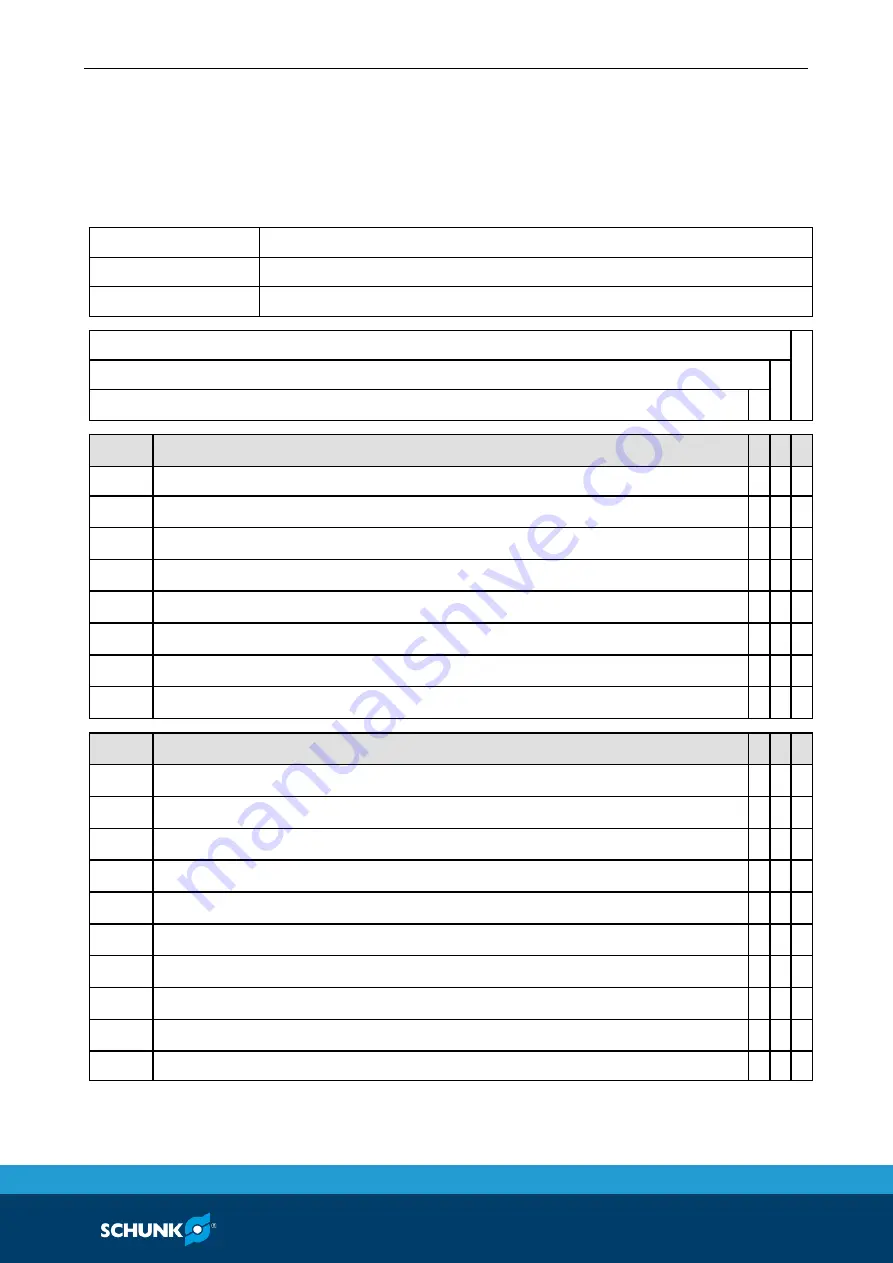
1. Description of the basic safety and health protection requirements, as per 2006/42/EC, 
Annex I, that apply to and are fulfilled for the scope of the incomplete machine: 


Product designation  VERO-S quick-change pallet system  

Type designation 

NSE-HT mini 88-20, NSE-HT mini 88-20-V10 

ID number 

1419192, 1419193 


To be provided by the System Integrator for the overall machine 


Fulfilled for the scope of the partly completed machine 


Not relevant 


1.1 

Essential Requirements 


1.1.1 

Definitions 

  X   

1.1.2 

Principles of safety integration 


1.1.3 

Materials and products 


1.1.4 

Lighting 


1.1.5 

Design of machinery to facilitate its handling 


1.1.6 

Ergonomics 


1.1.7 

Operating positions 


1.1.8 

Seating 


1.2 

Control Systems 


1.2.1 

Safety and reliability of control systems 


1.2.2 

Control devices 


1.2.3 

Starting 


1.2.4 

Stopping 


1.2.4.1  Normal stop 


1.2.4.2  Operational stop 


1.2.4.3  Emergency stop 


1.2.4.4  Assembly of machinery 


1.2.5 

Selection of control or operating modes 


1.2.6 

Failure of the power supply 

    X 


12 

Summary of Contents for VERO-S NSE mini 90-25

Page 1: ...Original Betriebsanleitung VERO S quick change pallet system NSE mini 90 25 NSE mini 90 25 V10 Assembly and Operating Manual Superior Clamping and Gripping...

Page 2: ...4 00 08 10 2020 en H D SCHUNK GmbH Co All rights reserved Dear Customer thank you for trusting our products and our family owned company the leading technology supplier of robots and production machin...

Page 3: ...e equipment 11 2 8 Notes on safe operation 11 2 9 Transport 12 2 10 Malfunctions 12 2 11 Disposal 12 2 12 Fundamental dangers 13 2 12 1 Protection during handling and assembly 13 2 12 2 Protection dur...

Page 4: ...area does not unlock properly 35 8 3 The quick change pallet system no longer opens quietly 35 9 Parts lists 36 9 1 NSE HT mini 88 20 ID 1419192 36 9 2 NSE HT mini 88 20 V10 ID 1419193 36 10 Assembly...

Page 5: ...manual Illustrations in this manual are provided for basic understanding and may differ from the actual product design In addition to these instructions the documents listed under 1 1 2 Page 6 are app...

Page 6: ...t with metal powders AM powder 250 000 cycles at operating temperatures 60 C without contact with metal powders AM powder 150 000 cycles at operating temperatures 60 C with contact with metal powders...

Page 7: ...essory kit NSE HT mini 88 20 V10 2 O rings 3 x 1 5 6 cover plugs 4 mounting screws M4 x 20 1 mounting screw M4 x 16 1 fitting screw M4 Accessories see catalog or home page when ordering separately Cla...

Page 8: ...ata 3 Page 17 The product is intended for industrial and industry oriented use Appropriate use of the product includes compliance with all instructions in this operating manual Not intended use The pr...

Page 9: ...material damage and or a significant reduction to the product s life span Make sure that the product is used only in the context of its defined application parameters 3 Page 17 Make sure that the prod...

Page 10: ...ete assembly and operating manual Observe the national safety regulations and rules and general safety instructions The following personal qualifications are necessary for the various activities relat...

Page 11: ...when handling hazardous substances Wear close fitting protective clothing and also wear long hair in a hairnet when dealing with moving components Notes on safe operation Incorrect handling of the per...

Page 12: ...e of malfunctions Immediately remove the product from operation and report the malfunction to the responsible departments persons Order appropriately trained personnel to rectify the malfunction Do no...

Page 13: ...ring operation Protection during handling and assembly Incorrect handling and assembly Incorrect handling and assembly may impair the product s safety and cause serious injuries and considerable mater...

Page 14: ...inadvertent reactivation Never rely solely on the response of the monitoring function to avert danger Until the installed monitors become effective it must be assumed that the drive movement is fault...

Page 15: ...d uncontrollably The product must never be operated outside its appropriate use WARNING The system clamps using spring force Risk of injury due to parts automatically moving to their end positions fol...

Page 16: ...ic safety notes 16 04 00 1411420_NSE mini 90 25 NSE mini 90 25 V10 en CAUTION Avoid contact between lubricant and the skin or eyes Wear personal protective equipment protective gloves and safety glass...

Page 17: ...n types Partial installation partially recessed full installation Operating temperature 15 C to 200 C Actuation temperature 15 C to 200 C Required level of cleanliness Cleanliness level 0 SAS0 accordi...

Page 18: ...stalling and connecting CAUTION Risk of injury from the product falling onto limbs while handling Wear personal protective equipment safety shoes and protective gloves 1 Check the flatness of the moun...

Page 19: ...ng pins 4 4 Page 24 Air bleeding for the piston chamber When connecting the quick change pallet systems it is important to note that the air can be completely bled from the piston chamber only via the...

Page 20: ...ge pallet systems are activated via jointly connected hose lines feed lines with the following minimum nominal widths for the hoses must be used Number of clamping modules min nominal hose width 1 4 4...

Page 21: ...ent e g positioning pin 12 g6 must not protrude deeper than 12 5 mm into the clamping module to avoid collision with the clamping pin At the same time the bore provides emergency access to the clampin...

Page 22: ...bore 4 H7 on the opposite side is precisely positioned in the mounting position The air connection is normally made via the coupling holes in the floor of the unit The NSE HT mini 88 20 V10 allows th...

Page 23: ...Assembly 04 00 1411420_NSE mini 90 25 NSE mini 90 25 V10 en 23 Installation specifications...

Page 24: ...force of the quick change pallet system is limited essentially by the tightness of the screw connection which connects the clamping pin to the pallet or the device This is why only screws of strength...

Page 25: ...causes problems in downstream processes because the clamping pin no longer protrude correctly into the clamping module Any clampings released must not lead to the permissible flatness being exceeded...

Page 26: ...Assembly 26 04 00 1411420_NSE mini 90 25 NSE mini 90 25 V10 en Usage arrangement of the different types of clamping pins...

Page 27: ...ing screw can cause the object to be clamped to fall down Only screws of the strength class specified in the operating manual may be used Observe the tightening torques Wear personal protective equipm...

Page 28: ...r the turbo and unlocking connection are engraved on the outside of the product These are used for orientation of the installation See pneumatic circuit diagram When controlling the quick change palle...

Page 29: ...laced immediately Only original SCHUNK spare parts may be used DANGER Danger of the object to be clamped falling down if it is not secured against uncontrolled movements If the clamping module is unlo...

Page 30: ...ed uncontrollably The product must never be operated outside of its appropriate use WARNING If the object to be clamped is placed on the closed clamping module during manual loading and unloading it d...

Page 31: ...no Wear parts set 1420073 WARNING Risk of injury due to unexpected movements of components when the power supply is switched on or there is residual energy in the system Before starting any work on th...

Page 32: ...rectly if the clamping slides move smoothly at minimum system pressure 5 bar Carry out regular visual functional checks Always immediately remove any impurities from the interfaces Maintenance interva...

Page 33: ...e again after 5 minutes The clamping module is sealed if the pressure gauge indicates a pressure drop of less than 0 2 bar min not sealed if the pressure gauge indicates a pressure drop of more than 0...

Page 34: ...ace or machine table and lifts the product 6 If disassembly is successful the bottom side unlocking connection can be pressurized with compressed gas using a compressed air pistol so that the clamping...

Page 35: ...case of leakage send the clamping module to SCHUNK for repair The clamping area does not unlock properly Possible cause Solution s Pressure below minimum Check operating pressure min 5 bar Hose diamet...

Page 36: ...1420073 NSE HT mini 88 20 ID 1419192 Item Designation Quantity 1 Body 1 2 Clamping slide 2 3 Piston 1 4 Cover 1 5 Locking screw 2 6 Cover plug 6 8 O ring 2 9 O ring 2 10 O ring 1 11 O ring 1 12 O rin...

Page 37: ...00 1411420_NSE mini 90 25 NSE mini 90 25 V10 en 37 Item Designation Quantity 8 O ring 2 9 O ring 2 10 O ring 1 11 O ring 1 12 O ring 1 13 O ring 1 14 O ring 2 15 Compression spring 6 16 Screw 4 17 Scr...

Page 38: ...Assembly Drawings 38 04 00 1411420_NSE mini 90 25 NSE mini 90 25 V10 en Assembly Drawings NSE HT mini 88 20 10 10 1...

Page 39: ...Assembly Drawings 04 00 1411420_NSE mini 90 25 NSE mini 90 25 V10 en 39 NSE HT mini 88 20 V10 10 2...

Page 40: ...tion until conformity of the machine into which the partly completed machine is to be installed with the provisions of the Machinery Directive 2006 42 EC is confirmed Applied harmonized standards espe...

Page 41: ...To be provided by the System Integrator for the overall machine Fulfilled for the scope of the partly completed machine Not relevant 1 1 Essential Requirements 1 1 1 Definitions X 1 1 2 Principles of...

Page 42: ...parts X 1 3 8 1 Moving transmission parts X 1 3 8 2 Moving parts involved in the process X 1 3 9 Risks of uncontrolled movements X 1 4 Required characteristics of guards and protective devices 1 4 1 G...

Page 43: ...ation and information devices X 1 7 1 2 Warning devices X 1 7 2 Warning of residual risks X 1 7 3 Marking of machinery X 1 7 4 Instructions X 1 7 4 1 General principles for the drafting of instruction...

Page 44: ...supplemented from here forward 4 Supplementary essential health and safety requirements to offset hazards due to lifting operations X 5 Supplementary essential health and safety requirements for machi...

Reviews: