background image

Function 


44 

02.00|1416054_ROTA-M2 + 2 |en-US 


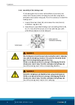
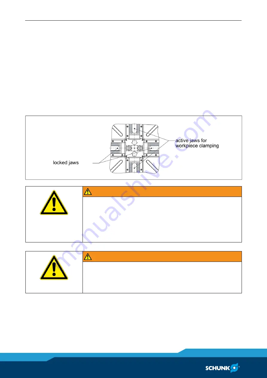
Assembly of the locking cover 

If a clamping structure is to be realized that only contains one 
active level of jaws (centric clamping vise and vise) using fixed 
workpiece stops and/or stop jaws, then it is necessary to install the 
locking cover: 

1  Loosen the screws (item 33) and remove the cover (item 3) 

with the O-ring (item 37). 

2  Install the pre-assembled locking cover (consisting of items 61, 

62, 72, 73) so that the arrows are in line with the jaws with 
which the workpiece is to be clamped. 


WARNING 

The locking cover must be used when using the centric clamping 
vise and vise clamping structure. This prevents the lathe chuck 
gear from moving/staying against the stop. 
If this is not observed, there is a danger of damaging the lathe 
chuck and a risk of injury from the workpiece being flung out. 

Use of the locking cover in the corresponding direction. 


WARNING 

Only O.D. clamping is permissible when using a locking cover. 
If this is not observed, there is a danger of damaging the lathe 
chuck and a risk of injury from the workpiece being flung out. 

Use of the locking cover only for O.D. clamping. 


6.6.2 

Summary of Contents for ROTA-M flex 2+2 1000

Page 1: ...Translation of Original Operating Manual Manual Lathe Chuck ROTA M flex 2 2 Assembly and Operating Manual Superior Clamping and Gripping ...

Page 2: ... All rights reserved Dear Customer Dear Customer Thank you for putting your trust in our products and our family owned company the leading technology supplier of robots and production machines Our team is always available to answer any questions on this product and other solutions We look forward to your challenging questions We will find a solution Best regards Your SCHUNK team H D SCHUNK GmbH Co...

Page 3: ... operation 13 2 10 Transport 14 2 11 Malfunctions 14 2 12 Disposal 14 2 13 Fundamental dangers 14 2 13 1 Protection during handling and assembly 15 2 13 2 Protection during commissioning and operation 15 2 13 3 Protection against dangerous movements 16 2 13 4 Notes on particular risks 16 3 Technical data 19 3 1 Lathe chuck data 19 3 2 Dimensions 20 3 3 Clamping force RPM diagrams 24 3 4 Calculatin...

Page 4: ...e from size 800 38 6 Function 39 6 1 Function and handling 39 6 2 Functional test before use 39 6 3 Replacement or enlargement of jaws 40 6 4 Clamping the workpiece 41 6 5 Compensation workpiece dimensions 42 6 6 Fixed workpiece stops and stop jaws 43 6 6 1 Assembly of the fixed workpiece stop 43 6 6 2 Assembly of the locking cover 44 6 6 3 Possibilities for clamping structure size 800 1200 45 7 M...

Page 5: ...ended to provide a basic understanding and may deviate from the actual version Besides this manual other documents which apply are those listed under 1 1 2 Page 6 Illustration of safety notes To make risks clear the following signal words and symbols are used for safety notes DANGER Danger to individuals Ignoring a safety note such as this will certainly lead to irreversible injury and even death ...

Page 6: ...ty If the product is used as intended the warranty is valid for 24 months from the date of delivery from the production facility or 500 000 cycles under the following conditions Refer to the applicable documents 1 1 2 Page 6 Observe the ambient conditions and operating conditions 2 6 Page 11 Observance of the specified care and maintenance instructions 7 Page 46 Parts touching the workpiece and we...

Page 7: ...0 8 T nuts with screws or 4 combi T nuts for variant with 60 fine serration 1 Assembly key 1 Actuation key or wrench from size 800 1 2 Eye bolt from size 800 1 Assembly and Operating Manual from size 800 1 Locking cover 12 16 T nuts with screw for table assembly size 1200 1 Centering pin 12 16 Covers for mounting screws size 1200 1 3 ...

Page 8: ...peed of rotation and the clamping force of the lathe chuck must be determined by the operator for the respective clamping task however the technical data engraved on the lathe chuck should never be exceeded Any other use is not as intended Reasonably foreseeable misuse Any use other than that defined under Appropriate Use or any use that goes beyond that definition is considered improper use and i...

Page 9: ...ess lack of concentration Clamping of insufficiently rigid workpieces clamping of workpieces that do not meet the specifications The rigidity of the workpiece is not sufficient to provide the lathe chuck with the necessary resistance that will allow the clamping force to build up Use for stationary or rotating processes where there is no workpiece or the workpiece is not clamped Use of chuck jaws ...

Page 10: ...ck face clamping points at a greater distance lead to greater surface pressure in the jaw guidance and can significantly reduce the clamping force If for design reasons the special chuck jaws are heavier than the top jaws assigned to the lathe chuck greater centrifugal forces must be taken into account when defining the required clamping force and the recommended speed of rotation The maximum reco...

Page 11: ...oys brass Safety data sheet for LINOMAX plus available at www schunk com Required ambient conditions and operating conditions Incorrect ambient and operating conditions can make the product unsafe leading to the risk of serious injuries considerable material damage and or a significant reduction to the product s life span Make sure that the product is only used within its defined application param...

Page 12: ...r has been instructed by the operator regarding the tasks entrusted to them and the potential dangers of inappropriate behavior The user may only carry out tasks that go beyond the use in normal operation if this is indicated in this manual and the operator has expressly instructed them to do so Order all work to be performed only by appropriately qualified personnel Personnel must have read and u...

Page 13: ...surfaces Wear protective gloves and safety goggles when handling hazardous substances Wear close fitting protective clothing and also wear long hair in a hairnet when dealing with moving components Notes on safe operation An incorrect manner of working can make the product unsafe and risks serious injuries and considerable material damage Avoid any manner of working that may interfere with the fun...

Page 14: ...esponsible departments persons Order appropriately trained personnel to rectify the malfunction Do not recommission the product until the malfunction has been rectified Test the product after a malfunction to establish whether it still functions properly and no increased risks have arisen Disposal Handling of disposal Incorrect handling during disposal can make the product unsafe and risks serious...

Page 15: ...nel For all work secure the product against accidental operation Observe the relevant accident prevention regulations Use suitable assembly and transport equipment and take precautions to prevent jamming and crushing Incorrect lifting of loads Falling loads can cause serious injuries and even death Stand clear of suspended loads and do not step within their swiveling range Never move loads without...

Page 16: ...t range To avoid accidents and or material damage human access to the movement range of the machine must be restricted Limit prevent accidental access for people in this area through technical safety measures The protection cover and protective fence must be rigid enough to withstand the maximum possible movement energy EMERGENCY STOP switches must be easily and quickly accessible Before commissio...

Page 17: ...o the machine Loose clothing or long hair may become caught on projecting parts of the lathe chuck and be drawn into the machine The machines and equipment must fulfill the minimum requirements of the EC Machinery Directive specifically they must have effective technical measures to protect against potential mechanical hazards Always wear tight fitting clothing and a hairnet when working on the ma...

Page 18: ...s when operating the chuck especially when working with machine tools and other technical equipment CAUTION Risk of damage due to incorrect choice of clamping position for chuck jaws on workpiece If an incorrect clamping position is chosen for the chuck jaws on the workpiece the base and top jaws may become damaged The T nuts for connecting the top jaws to the base jaws must not protrude beyond th...

Page 19: ...0 36 0 81 2 54 7 27 14 14 23 06 45 34 75 08 Centrifugal torque of base jaw kgm McGB 0 08 0 11 0 262 0 577 0 925 1 538 1 979 2 419 Spindle holder ISO 702 4 No 8 220 H6 No 11 300 H6 No 15 380 H6 No 15 380 H6 No 15 380 H6 Base plate Operating temperature 15 C to 60 C Ensure minimal weight for all jaws For the respective machining task the permissible speed of rotation for a given initial clamping for...

Page 20: ...Screw tightening torques 20 02 00 1416054_ROTA M2 2 en US Dimensions 3 2 ...

Page 21: ...Screw tightening torques 02 00 1416054_ROTA M2 2 en US 21 ...

Page 22: ...8 31 31 31 L mm 5 5 6 6 6 M mm 63 5 63 5 83 94 94 57 67 67 N mm transpor t M8 M8 M12 M16 M16 M16 M16 M16 O 45 45 45 45 45 P mm 20 5 19 5 20 5 19 5 25 26 26 26 27 27 27 Q mm 11 10 11 10 13 5 13 5 14 5 14 5 15 5 15 5 15 5 R1 min mm 11 5 13 1 11 5 13 1 16 7 14 18 8 18 8 13 6 13 6 13 6 R2 min mm 19 5 25 19 5 25 25 30 31 31 31 31 31 S max mm 283 4 335 9 432 4 534 1 663 1 832 6 1032 1 1232 2 SW mm 12 12...

Page 23: ...module 2 a 60 H7 60 H7 60 H7 b 27 17 17 c 8 8 8 d 343 5 443 5 543 5 e 14 7 13 11 25 f 22 5 22 5 22 5 g 75 75 75 h 160 160 160 i 22 G7 22 G7 22 G7 j 230 250 250 k 13 5 17 5 22 l 570 590 590 m 500 500 500 n 145 145 145 o 765 930 1050 p 535 550 550 q 45 45 45 r 25 25 25 s 9 9 9 t 14 14 14 v 23 23 23 ...

Page 24: ...diameter of the lathe chuck The lathe chuck is in perfect condition and lubricated with SCHUNK LINOMAX plus special grease If one or more of these prerequisites is modified the graphs will no longer be valid Lathe chuck setup for clamping force RPM graph FspB Jaw clamping force S Center of gravity rs Center of gravity radius amax Max jaw eccentricity of center of gravity in axial direction Fmax Ma...

Page 25: ...crew tightening torques 02 00 1416054_ROTA M2 2 en US 25 Clamping force RPM graph for ROTA M flex 2 2 315 Clamping force RPM graph for ROTA M flex 2 2 400 Clamping force RPM graph for ROTA M flex 2 2 500 ...

Page 26: ...rew tightening torques 26 02 00 1416054_ROTA M2 2 en US Clamping force RPM graph for ROTA M flex 2 2 630 Clamping force RPM graph for ROTA M flex 2 2 800 Clamping force RPM graph for ROTA M flex 2 2 1000 ...

Page 27: ... top jaw kg ssp Safety factor for clamping force mB Mass of chuck jaw set kg sz Safety factor for machining Mc Centrifugal torque kgm Σs Max clamping force of lathe chuck N kgm 9 81 Nm Calculation of the required clamping force at a specified speed of rotation The initial clamping force Fsp0 is the total force impacting radially on the workpiece via the jaws due to actuation of the lathe chuck dur...

Page 28: ...nimum clamping force Fspmin Consequently the workpiece is released spontaneously Do not exceed the calculated RPM Do not fall below the necessary minimum clamping force Reduction in effective clamping force by the magnitude of the total centrifugal force for gripping from the outside inwards The required effective clamping force for machining Fsp is calculated from the product of the machining for...

Page 29: ...ravity radius and the rpm NOTICE For safety reasons in accordance with DIN EN 1550 the centrifugal force may be a maximum of 67 of the initial clamping force The formula for the calculation of the total centrifugal force Fc is For this n is the given speed of rotation in RPM The product mB rs is referred to as the centrifugal torque Mc In case of toolholders with split chuck jaws i e with base jaw...

Page 30: ...radius of top jaw rsAB 0 107 m application specific Safety factor Sz 1 5 according to VDI 3106 Safety factor Ssp 1 5 according to VDI 3106 Note Masses of the jaw mounting screws and T nuts are not taken into account First the required effective clamping force Fsp is calculated using the machining force stated Initial clamping force during shutdown Calculation of total centrifugal force For two par...

Page 31: ...uring shutdown NOTICE For safety reasons the calculated permissible RPM may not exceed the maximum RPM inscribed on the lathe chuck Example of calculation Permissible RPM for a given effective clamping force The following data is known from previous calculations Initial clamping force during shutdown Fsp0 17723 N Machining force for machining job Fspz 3000 N application specific Total centrifugal ...

Page 32: ...ion being achieved see DIN EN 1550 6 2 e This applies particularly to high speeds asymmetrical workpieces or the use of various top jaws as well as uneven application of lubricants In order to prevent damage resulting from these residual risks the entire rotor is to be dynamically balanced in accordance with DIN ISO 21940 11 Screw tightening torques Tightening torques for mounting screws used to s...

Page 33: ...ns in the system CAUTION Risk of injury due to sharp edges and rough or slippery surfaces Wear personal protective equipment particularly protective gloves 1 Checking the spindle nose and or machine table 5 2 Page 34 2 Lathe chuck assembly Assembly of the lathe chuck with cylindrical recess 5 3 1 Page 35 if required Assembly preparation for lathe chuck with reduction or expansion adapter plate 5 3...

Page 34: ...the mount must not exceed 0 005 mm and the maximum axial run out error in the contact surfaces must not exceed 0 005 mm The flat surface of the spindle must also be checked for flatness using a straight edge Make sure that the surface area of the flat surface is deburred at the bore holes and is clean Machine table Check the machine table and ready machined intermediate flange for radial and axial...

Page 35: ... recess NOTE If the interface of the machine spindle and lathe chuck is identical assembly is carried out without assembly preparation If the interface of the machine spindle deviates from the interface of the lathe chuck a connecting flange must be affixed before assembly See 5 3 2 Page 37 or 5 3 3 Page 38 5 3 5 3 1 ...

Page 36: ...ng equipment in alignment with the spindle center 4 Insert and slightly tighten the mounting screws 5 Check the lathe chuck for concentricity and axial run out accuracy see Fig Lathe chuck assembly E 5 3 Page 35 and if necessary align at the outer diameter with light taps using a hammer 6 Tighten the mounting screws item 30 with a torque wrench Observe the maximum admissible torques 4 Page 32 7 Re...

Page 37: ...er plate must be used Fasten this adapter plate to the spindle nose prior to lathe chuck assembly 1 Before assembly of the adapter plate remove any dirt or chips from the machine spindle and from the centering mount and contact surface of the adapter plate 2 An adapter plate produced by the user must be finished on the machine spindle and balanced prior to lathe chuck assembly 3 After assembly ens...

Page 38: ...h the supplied mounting screws 3 Lathe chuck assembly then follows 5 3 1 Page 35 Assembly preparation for lathe chuck with base plate on machine table from size 800 Insert the T nuts item 76 into the grooves provided in the machine table Then lift the toolholder and supplied eye bolts onto the machine table Position via the centering pins item 64 Align the chuck and then fasten using the screws it...

Page 39: ...ed to mount standard jaws as well as special jaws for complicated workpiece shapes The top jaws are moved or changed in the open clamping position WARNING Clamping further above the lathe chuck surface results in a lower clamping force If the workpiece is released in an uncontrolled manner there is a risk of personal injury and damage to the system Refer to the Technical data chapter Functional te...

Page 40: ...the top jaws the serration has to be cleaned and greased with SCHUNK LINOMAX plus special grease Tighten the jaw mounting screws screw quality 12 9 to the specified torque 4 Page 32 NOTICE Tighten the mounting screws of the top jaws with a torque wrench Never tighten the Allen key with an extension pipe or by hitting it with a hammer Turning chuck jaws For maximum clamping repeat accuracy the chuc...

Page 41: ... must be completely recessed only then is permissible clamping achieved WARNING When a workpiece is clamped the indicator pins must be completely recessed If the indicator pins are not completely recessed there is a risk that the lathe chuck gear will move stay against the stop Risk of injury due to the workpiece being ejected from the machine If the indicator pin protrudes do not clamp the lathe ...

Page 42: ... jaw stroke and is also the area within which the indicator pins are completely recessed Using the compensation function the lathe chuck can accommodate workpieces that have the dimension X compensation per jaw when their side lengths are placed perpendicular to each other Example ROTA M flex 2 2 315 Distance between chuck jaws when the lathe chuck is open 100 mm Center of overall jaw stroke 100 m...

Page 43: ...der rotation WARNING If fixed workpiece stops are used for clamping on the lathe chuck observe the maximum actuation moment permitted depending on the clamping structure If it is exceeded there is a danger of damaging the lathe chuck and a risk of injury from the workpiece being flung out Observe the specified maximum actuation moment for the clamping structure used Assembly of the fixed workpiece...

Page 44: ...line with the jaws with which the workpiece is to be clamped WARNING The locking cover must be used when using the centric clamping vise and vise clamping structure This prevents the lathe chuck gear from moving staying against the stop If this is not observed there is a danger of damaging the lathe chuck and a risk of injury from the workpiece being flung out Use of the locking cover in the corre...

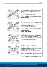
Page 45: ...ce on the workpiece 90 kN USE LOCKING COVER FOR O D CLAMPING ONLY 2 stop jaws 2 fixed workpiece stops The individual stop jaws each press the workpiece against the fixed workpiece stops with 50 of the clamping force generated by the actuation moment max actuation moment 125 Nm max clamping force on the workpiece 180 kN 3 stop jaws 1 fixed workpiece stops The opposite stop jaws each press against t...

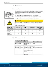
Page 46: ...er lubrication CAUTION Allergic reactions if lubricating grease comes into contact with the skin Wear protective gloves Chuck size greasing area 260 315 400 500 630 800 1000 1200 under jaws 2 and 4 6 10 15 20 Spindle extension 4 6 8 8 Maintenance intervals Lubricating the greasing areas Lubrication interval Demands To be carried out by every 25 hours normal use of coolant User every 8 hours high u...

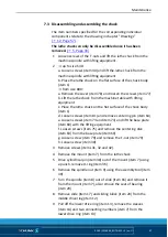
Page 47: ...e flat surface of the chuck body item 1 d Loosen screws item 81 and remove centering pin item 64 e Loosen screws item 73 and item 74 and lift the base plate item 60 with the lifting equipment f Loosen screws item 75 and remove the centering disk item 63 from the base plate item 60 g Loosen screw item 79 and remove the T nut item 79 h Loosen screw item 30 3 Remove screws items 31 32 and 42 4 Remove...

Page 48: ...springs item 38 from the chuck body item 1 15 Remove screws item 34 and pull off the cover plates items 23 and 24 16 Turn over the chuck body item 1 17 Remove screws item 33 and then remove the cover item 3 with the O ring item 37 and wipers items 21 and 22 18 Remove the O ring sections item 26 and sealing elements item 25 19 Remove the base jaws item 2 20 Remove the bolts item 18 Degrease and cle...

Page 49: ... also incorporated into the groove in the cover plate items 23 and 24 CAUTION Use the cover plates item 23 on guideways 1 and 4 6 Fix the cover plates items 23 and 24 in place with screws item 34 7 Press the projecting O ring sections item 26 into the gap between the chuck body item 1 and the sealing element item 25 8 Secure the wipers items 21 and 22 with screws item 33 beside the guideways 9 Pre...

Page 50: ...ng members item 6 into the holes The marking must be visible and point in the direction of guideway 1 20 Remove the cylindrical pins item 48 on guideway 4 21 Insert the sleeves item 14 into the lower drive ring item 13 the chamfers must point downwards 22 Insert the locking bolts item 15 into the holes of the drive rings 23 Insert the slide item 17 with pin into the groove of the center drive ring...

Page 51: ...e cover plate items 23 and 24 against the mount item 7 tighten the screws item 34 from size 800 36 Fasten the mount item 7 to the chuck body item 1 with screws item 30 37 Fasten centering disk item 63 with screw item 75 to the base plate item 60 38 Place the assembled base plate item 60 on the mount item 7 Carry out centering via the centering disk item 63 and alignment via the T nut item 80 39 Sc...

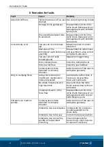
Page 52: ...es Dirty jaw interface Clean the jaw interface Compensation stroke depleted in clamping situation Adjust position of top jaws to workpiece geometry Drop in clamping force Lathe chuck lubrication insufficient maintenance interval exceeded Lubricate the lathe chuck if necessary disassemble clean and relubricate No stroke movement with high repetition Open and close the lathe chuck several times with...

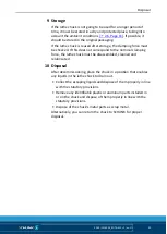
Page 53: ...espond to the nominal clamping force the lathe chuck must be disassembled cleaned and relubricated Disposal After decommissioning place the chuck in a position that enables any liquids in the lathe chuck to drain out Collect the escaping liquids and dispose of them properly in line with the statutory provisions Remove any identifiable plastic or aluminum parts installed in or on the chuck and disp...

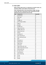
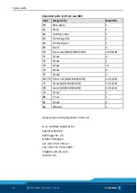
Page 54: ...em Designation Quantity 1 Chuck body 1 2 Base jaws 4 3 Cover 1 5 Wedge bar 4 6 Connecting member 4 7 Mount 1 8 Spindle 1 9 Spindle nut 1 11 Upper drive ring 1 12 Middle drive ring 1 13 Lower drive ring 1 14 Sleeve 4 15 Locking bolt 4 16 Slide with thread 1 17 Slide without thread 1 18 Bolt 4 19 Indicator pin 2 20 Sliding block 1 21 Right wiper 4 22 Left wiper 4 23 Wiper plate with hole 2 24 Wiper ...

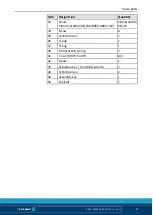
Page 55: ...tity 33 Screw 260 315 400 500 630 800 1000 1200 28 36 44 60 68 76 34 Screw 8 35 Cylindrical pin 1 36 O ring 1 37 O ring 1 38 Compression spring 2 41 T nut SV90 SV60 8 4 42 Screw 1 47 Actuation key from 800 wrench 1 48 Cylindrical pin 2 49 Assembly key 1 50 Eye bolt 1 ...

Page 56: ...screw 800 1000 1200 24 32 40 71 Screw 4 72 Screw 1 73 Screw 16 74 Screw 6 75 Screw 4 23776 T slot nut 800 1000 1200 12 12 16 77 Screw 800 1000 1200 12 12 16 78 Cover 800 1000 1200 12 12 16 79 Screw 1 80 T nut 1 81 Screw 2 82 Adapter 1 Accessories and replacement orders at H D SCHUNK GmbH Co Spanntechnik KG Lothringer Str 23 D 88512 Mengen Tel 49 7572 7614 0 Fax 49 7572 7614 1099 info de schunk com...

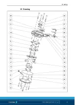
Page 57: ...Drawing 02 00 1416054_ROTA M2 2 en US 57 Drawing 12 ...

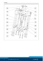
Page 58: ...Drawing 58 02 00 1416054_ROTA M2 2 en US ...

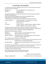
Page 59: ...at the machine into which the partly completed machinery is to be installed complies with the provisions of the Machinery Directive 2006 42 EC Applied harmonized standards especially DIN EN ISO 12100 2011 03 Safety of machinery General principles for design Risk assessment and risk reduction DIN EN 1550 2008 11 Machine tools safety Safety requirements for the design and construction of work holdin...

Page 60: ...ability of controllers X 1 2 2 Controls X 1 2 3 Starting X 1 2 4 Stopping X 1 2 4 1 Normal stopping X 1 2 4 2 Operational stopping X 1 2 4 3 Emergency stopping X 1 2 4 4 All machines X 1 2 5 Selecting control and operating modes X 1 2 6 Malfunction of the energy supply X 1 3 Protective measures against mechanical hazards 1 3 1 Risk of loss of stability X 1 3 2 Risk of breakage during operation X 1...

Page 61: ...on facilities X 1 7 1 2 Warning facilities X 1 7 2 Warning against residual risks X 1 7 3 Labeling the machines X 1 7 4 Operating manual X 1 7 4 1 General principles for writing the operating manual X 1 7 4 2 Content of the operating manual X 1 7 4 3 Sales brochures X Structure from Appendix 1 2 Additional basic safety and health protection requirements for specific categories of machine X 2 1 Foo...

Reviews: