background image

Assembly

36

06.00 | PPU-P | Assembly and Operating Manual | en | 389323

Ø

Check shock absorption during operation and correct, if necessary.

The shock absorber is set correctly when the unit reaches its
end position quickly and without mechanical impact.

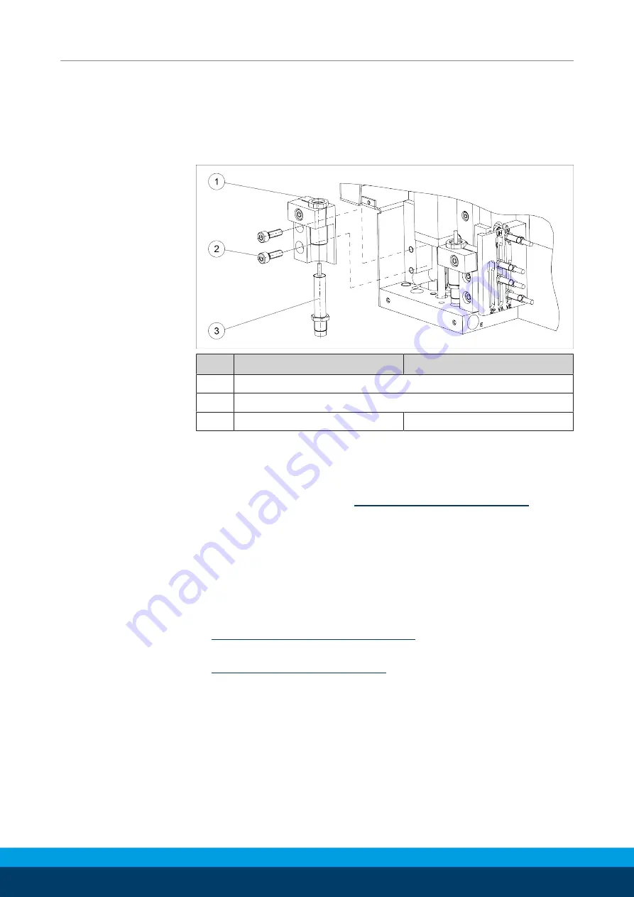
4.7.2 Replacement of shock absorbers

Item

PPU-P 10

PPU-P 30

1

Mount

3

Shock absorbers

2

Screw ISO 4762 M5x16

Screw ISO 4762 M6x20

Ø

Unscrew the front cover plate from the cover.

Ø

Remove the entire mounting assembly, with the clamp, sleeve
and shock absorber.

Ø

Write down dimension A 

Adjustment of shock absorbers

 [

}

 35].

Ø

Unscrew the shock absorber (110) from the sleeve and replace
with a new shock absorber.

Ø

Set to dimension A and fix with a lock nut.

Ø

Reinstall the entire mounting assembly, with the clamp, sleeve
and shock absorber, pressing the assembly onto the surface of
the base plate.

Ø

Check the position of the end position and correct if necessary

Adjustment of vertical end positions

 [

}

 30].

Ø

Readjust shock absorber if necessary

Adjustment of shock absorbers

 [

}

 35].

Summary of Contents for PPU-P

Page 1: ...Translation of the original manual Assembly and Operating Manual PPU P Pick and Place Unit ...

Page 2: ...ns for the purpose of technical improvement Document number 389323 Version 06 00 07 05 2020 en SCHUNK GmbH Co KG All rights reserved Dear Customer thank you for trusting our products and our family owned company the leading technology supplier of robots and production machines Our team is always available to answer any questions on this product and other solutions Ask us questions and challenge us...

Page 3: ... 12 2 10 Malfunctions 13 2 11 Disposal 13 2 12 Fundamental dangers 13 2 12 1 Protection during handling and assembly 14 2 12 2 Protection during commissioning and operation 14 2 12 3 Protection against dangerous movements 15 2 12 4 Protection against electric shock 15 2 13 Notes on particular risks 16 3 Technical Data 17 3 1 Anti fall device 18 3 2 Valve and control specifications 18 4 Assembly 19...

Page 4: ...1 Steps for commissioning 38 5 2 2 First steps 38 5 3 Actuation operation 39 5 3 1 Standard sequence 39 5 3 2 Sequence with actuation of stand by position 41 6 Troubleshooting 46 6 1 No Pick Place motion 46 6 2 Cycle speed is not reached 46 6 3 Rough sequence 47 6 4 Impact in the end positions 47 6 5 Module does not achieve the opening and closing times 47 7 Maintenance 48 7 1 Shock absorbers 48 7...

Page 5: ...s manual Illustrations in this manual are provided for basic understanding and may differ from the actual product design In addition to these instructions the documents listed under Applicable documents 6 are applicable 1 1 1 Presentation of Warning Labels To make risks clear the following signal words and symbols are used for safety notes DANGER Danger for persons Non observance will inevitably c...

Page 6: ...wing accessories which must be ordered separately are required for the product Sensors Base plate mounting kit Anti fall device Energy hose mounting kit Adapter plate mounting kit A wide range of accessories are available for this product For information regarding which accessory articles can be used with the corresponding product variants see catalog data sheet 1 1 4 1 Sensors Overview of the com...

Page 7: ...ctuation or overload The rod lock may only be triggered and unlocked when the product has been shut down or is in its waiting position Observe the specifications for the static holding force The occuring forces in clamped condition may not exceed the retention force In the event of a dynamic load or overload e g drop in pressure during movement the clamping cartridge must be checked and replaced i...

Page 8: ... mounting kit AS PPU P30 APL 0314706 For adaptation to the connecting diagram of the GEMOTEC system Parts included Connecting screws for mounting on unit 1 2 Warranty If the product is used as intended the warranty is valid for 24 months from the ex works delivery date under the following conditions Observe the specified maintenance and lubrication intervals Observe the ambient conditions and oper...

Page 9: ...on in a machine system The applicable guidelines must be observed and complied with The product is intended for industrial and industry oriented use Appropriate use of the product includes compliance with all instructions in this manual 2 2 Not intended use It is not intended use if the product is used for example as a pressing tool stamping tool lifting gear guide for tools cutting tool clamping ...

Page 10: ...erable material damage and or a significant reduction to the product s life span Make sure that the product is used only in the context of its defined application parameters Technical Data 17 Ensure that maintenance and lubrication intervals are observed Maintenance 48 Make sure that the environment is free from splash water and vapors as well as from abrasion or processing dust Exceptions are pro...

Page 11: ...ted tasks recognize and avoid possible dangers and knows the relevant standards and regulations Instructed person Instructed persons were instructed by the operator about the delegated tasks and possible dangers due to improper behaviour Service personnel of the manufacturer Due to its technical training knowledge and experience service personnel of the manufacturer is able to perform the delegate...

Page 12: ...orrosive media This does not apply to products that are designed for special environments Eliminate any malfunction immediately Observe the care and maintenance instructions Observe the current safety accident prevention and environmental protection regulations regarding the product s application field 2 9 Transport Handling during transport Incorrect handling during transport may impair the produ...

Page 13: ...disposal The incorrect handling of disposal may impair the product s safety and cause serious injuries as well as considerable material and environmental harm Follow local regulations on dispatching product components for recycling or proper disposal 2 12 Fundamental dangers General Observe safety distances Never deactivate safety devices Before commissioning the product take appropriate protectiv...

Page 14: ...evention rules Use suitable assembly and transport equipment and take precautions to prevent jamming and crushing Incorrect lifting of loads Falling loads may cause serious injuries and even death Stand clear of suspended loads and do not step into their swiveling range Never move loads without supervision Do not leave suspended loads unattended 2 12 2 Protection during commissioning and operation...

Page 15: ...e through technical safety measures The protective cover and protective fence must be rigid enough to withstand the maximum possible movement energy EMERGENCY STOP switches must be easily and quickly accessible Before starting up the machine or automated system check that the EMERGENCY STOP system is working Prevent operation of the machine if this protective equipment does not function correctly ...

Page 16: ... maintenance valves WARNING Risk of injury due to unexpected movements If the power supply is switched on or residual energy remains in the system components can move unexpectedly and cause serious injuries Before starting any work on the product Switch off the power supply and secure against restarting Make sure that no residual energy remains in the system WARNING Danger of crushing and impacts ...

Page 17: ...evable cycle time ms See catalog Max permissible number of cycles rpm 95 75 Max horizontal stroke adjustment per side mm 12 18 Max independent vertical stroke adjustment mm 15 20 Max vertical stroke difference mm 8 10 Installation position horizontal Operating data for compressed air connection Pressure medium Compressed air compressed air quality according to ISO 8573 1 7 4 4 Min pressure bar 4 M...

Page 18: ...al control valves 4 x 3 2 directional control valve monostably vented 4 x 3 2 directional control valve monostably vented Nominal flow 200 l min 400 l min response time on 28 ms 28 ms Response time off 8 ms 8 ms Recommended cycle time of the PLC 1 ms 1 ms If the digital input signals are wired directly to the PLC input module make sure that this does not exceed a maximum cycle time of 5 ms Due to ...

Page 19: ... for evenness of the mounting surface Dimensions in mm Edge length Permissible unevenness 100 0 02 100 0 05 Mounting Mounting of the unit The unit must be mounted on the floor space below The following mounting materials are necessary for installation of the unit and must be provided by the customer Mounting material Item Designation PPU P 10 PPU P 30 1 Screw ISO 4762 M8 2x M10 4x 2 Cylindrical pi...

Page 20: ...e mounting kit Mounting material for base plate option provided by customer Item Designation PPU P 10 PPU P 30 2 Screw ISO 4762 M8 4x M10 4x 1 Cylindrical pin ISO 8734 Ø5m6 2x Ø6m6 2x 3 Base plate 4 Screw ISO 4762 M8x20 2x M10x30 4x 5 Cylindrical pin ISO 8734 Ø5m6 l 24mm 2x Ø6m6 l 30mm 2x must be provided by customer NOTE Always observe screw tightening torques Select the suitable screw tightening...

Page 21: ...entering sleeve 0313367 0313368 included in scope of delivery CAUTION Please note the permissible range of the center of mass of the load Always mount loads with the cantilever arm retracted Select the suitable screw tightening torque for mounting of the loads on the unit in accordance with the generally applicable directives for screw connections When mounting loads only the maximum permissible m...

Page 22: ...l en 389323 Permissible additional loads when mounting the load permissible moments when attaching loads Load PPU P 10 PPU P 30 Mmax Nm 15 45 permissible range of the center of mass of the load Dimension PPU P 10 PPU P 30 A mm 50 80 B mm 25 30 C mm 25 30 ...

Page 23: ...ecure against restarting Make sure that no residual energy remains in the system CAUTION Pressure medium The unit must not under any circumstances be operated with oiled air before operation with unoiled air washing out of factory lubrication CAUTION Observe the requirements for the air supply Technical Data 17 CAUTION The lengths of the hoses from the valve to the unit affect the cycle time The h...

Page 24: ...em Connection Plug in connection for hose Da mm PPU P 10 PPU P 30 1 Compressed air connection C D Actuation of horizontal drive C Retract D Extend 4 6 2 Compressed air connection A Actuation for raising vertical drive 6 6 3 Compressed air connection B Actuation for lowering of vertical drive 6 6 ...

Page 25: ...e product has been shut down or is in its waiting position Observe the specifications for the static holding force The occuring forces in clamped condition may not exceed the retention force In the event of a dynamic load or overload e g drop in pressure during movement the clamping cartridge must be checked and replaced if necessary WARNING The rod lock is not a safety component for personal prot...

Page 26: ...r as it will go into the designated bore hole Ø Push the rod 2 into the designated hole from below and screw it into the thread Ø Secure the thread Ø Remove the screw from the locking cartridge and screw in the air connection 1 4 4 3 Mounting of energy hose mounting kit AS PPU P ES Mounting of energy hose mounting kit Item PPU P 10 PPU P 30 3 Mount 6 Cable protection sleeve pre mounted 5 Threaded ...

Page 27: ...mounting kit AS PPU P APL Item PPU P 10 PPU P 30 91 Adapter plate 100 Centering sleeve 195 Screw ISO 4762 M4x10 2x Screw ISO 4762 M5x12 2x Optional adapter plate included Included CAUTION See instructions for attachment of loads Attachment of loads 21 4 5 Adjusting end positions and shock absorbers The end positions can be adjusted separately from each other both horizontally and vertically PPU P ...

Page 28: ...ting Manual en 389323 Key The key 1 included with the unit can be used to adjust the vertical end position and the shock absorbers The key is integrated in the front wall of the cover CAUTION The key is designed only for low tightening torques ...

Page 29: ...mitted only with all covers in place Ø Actuate the desired end position by pressurizing the compressed air connections A B and C D or actuate manually Ø Slightly loosen the 3 clamping screws 2 on the side of the end position to be adjusted NOTE For exact positioning horizontal pressure pneumatic or manual must be applied to the cantilever arm in the direction of the respective end position Ø Set t...

Page 30: ...sting the end positions vertically Depressurize the unit Ø Unscrew the cover plate of the paneling Ø Approach the desired end position manually Ø Slightly loosen the attachment screw 1 on the side of the end position to be adjusted NOTE For precise positioning vertical pressure must be applied to the slide from above Ø Place the end position in the desired position by turning the sleeve 2 Ø Tighte...

Page 31: ...Operating Manual and catalog data sheet The Assembly and Operating Manual and catalog data sheet are included in the scope of delivery for the sensors and are available at schunk com Information on handling sensors is available at schunk com or from SCHUNK contact persons The sensors required for operation are factory installed MMS sensors for sensing the horizontal position of the piston are avai...

Page 32: ... sensors Item Description PPU P 10 PPU P 30 121 IN sensor X mm Distance between UH and VA sensor upper end position 15 23 X mm Distance between UH and VE sensor upper end position 15 23 Y mm Switching distance approx 0 5 approx 0 8 Sensor assignment Sensor Description VE Sensor for rear end position home position extension arm returned VA Sensor for front end position extension arm extended UH Swi...

Page 33: ...VA sensor against the control cam from below until there is a signal at the output Ø Secure position by tightening the sensor Adjusting sensors for UV and UH switching points Back stops of the vertical end positions have been adjusted Adjustment of vertical end positions 30 Sensors of end positions have been adjusted see above The unit has been depressurized Ø Unscrew the cover plate of the paneli...

Page 34: ...rs MMS CAUTION Sensor can be damaged during assembly Do not exceed the maximum tightening torque of 10 Ncm Mounting of Sensor MMS Ø Unscrew the front cover plate from the cover Ø Tilt sensor slightly to insert it into the monitoring groove Ø Adjust sensor to desired monitoring position and fasten with set screw ...

Page 35: ...ock absorbers can be adjusted in installed state Re adjustment of the end positions is not necessary The horizontal end positions have been set Adjustment of horizontal end positions 29 The stops for the vertical end positions have been set Adjustment of vertical end positions 30 CAUTION The vertical stop of the unit is the sleeve Never unscrew the shock absorber so far that it extends past the sl...

Page 36: ...ate from the cover Ø Remove the entire mounting assembly with the clamp sleeve and shock absorber Ø Write down dimension A Adjustment of shock absorbers 35 Ø Unscrew the shock absorber 110 from the sleeve and replace with a new shock absorber Ø Set to dimension A and fix with a lock nut Ø Reinstall the entire mounting assembly with the clamp sleeve and shock absorber pressing the assembly onto the...

Page 37: ...Regulator valve for vertical stroke PPU P 30 only NOTE The adjusting screw can be accessed through a hole in the cover arrows Ø Adjust the horizontal stroke by means of the regulator valve 1 so that the forward and return motions of the cantilever arm take place at the same speed Ø Adjust the vertical stroke by means of the regulator valve 2 so that the cycle time of the standard process Standard ...

Page 38: ...hat it is in perfect operating condition after having checked for compliance with all permissible operating parameters Further information 2 Attachment of loads 21 5 2 2 First steps Proceed as follows to commission the unit Ø Adjust horizontal end positions Adjustment of horizontal end positions 29 Ø Adjust vertical end positions Adjustment of vertical end positions 30 Ø Adjust sensor IN Mounting ...

Page 39: ...Handling and operation 06 00 PPU P Assembly and Operating Manual en 389323 39 5 3 Actuation operation 5 3 1 Standard sequence Actuation diagram for standard Pick Place sequence ...

Page 40: ... force driven then on the curve radius Ø Sensor reaches switching point UV Maintain actuation of both valves Roller is at start of curve Cantilever arm moves only horizontally Ø Sensor UV leaves The roller reaches the front curve radius leaves the switching range of the sensor UV force driven Actuation of valve A B raise lower Vertical motion is initiated Cantilever arm moves first out of the curv...

Page 41: ...rve radius then vertically downward Ø Back end position home position is reached Horizontal Cantilever arm retracted pressurized connection C Vertical Cantilever arm lowered pressurized connection B Sensor allocation VE Ø Stand by time Execution of additional motions gripping etc external start if applicable restart of Pick Place cycle 5 3 2 Sequence with actuation of stand by position The unit ca...

Page 42: ...Handling and operation 42 06 00 PPU P Assembly and Operating Manual en 389323 Actuation of stand by positions ...

Page 43: ...orizontal Cantilever arm retracted pressurized connection C Vertical Cantilever arm lowered pressurized connection B Sensor allocation VE Ø PPU P in back end position Actuation of valve B A lower raise Move to back stand by position Cantilever arm moves vertically upward Ø Sensor reaches switching point UH Maintain actuation of both valves To move to the stand by position the signal of the sensor ...

Page 44: ...e roller reaches the front curve radius leaves the switching range of the sensor UV force driven Actuation of valve A B raise lower Vertical motion is initiated Cantilever arm moves first out of the curve radius then vertically downward Ø Front end position is reached Horizontal Cantilever arm extended pressurized connection D Vertical Cantilever arm lowered pressurized connection B Sensor allocat...

Page 45: ...tion Actuation of valve C D forward stroke return stroke Start Pick Place cycle from the front stand by position Cantilever arm continues motion on curved path Ø Sensor reaches switching point UV Maintain actuation of both valves Roller is at start of curve Cantilever arm moves only horizontally Ø Sensor UV leaves The roller reaches the back curve radius leaves the switching range of the sensor UV...

Page 46: ... Check valve switching times and consult SCHUNK contact person if necessary Shock absorber extended too far Readjustshock absorber setting Adjustment of shock absorbers 35 Fallen short of nominal pressure Check air supply Technical Data 17 Permissible lengths of connection lines exceeded Keep compressed air lines between the product and directional control valve as short as possible Air connection...

Page 47: ...stment of regulator valves 37 Slow down sequence by adjusting UH sensor upwards Operating pressure too high Check maximum pressure of air supply Technical Data 17 6 4 Impact in the end positions Possible cause Corrective action Shock absorber defective Change and adjust shock absorber Adjustment and replacement of shock absorbers 35 Shock absorber postponed too far Readjustshock absorber setting A...

Page 48: ...ceeding the permissible cycle frequency can significantly reduce the life of the shock absorbers Technical Data 17 and Adjustment of shock absorbers 35 Recommended replacement intervals for shock absorbers Size PPU P 10 PPU P 30 Interval Mio cycles 3 5 For replacement instructions Replacement of shock absorbers 36 7 2 Lubricants Lubrication points We recommend the lubricants listed During maintena...

Page 49: ... if they are removed or replaced Ø Check regularly for correct function and leaks replace if necessary Further information 2 Spare parts 51 7 4 Lubricate the guides Lubrication points of the guides Ø Lubricate horizontal and vertical guide at the specified lubrication points Recommended lubrication intervals for guides Size PPU P 10 30 Interval Mio cycles 10 ...

Page 50: ...avoided in operation Replace clamping cartridge Item Designation ID number PPU P 10 PPU P 30 2 Rod 5520567 5522706 3 Clamping cartridge 9955686 9954333 Disassembly Ø remove air connection M5 1 Ø unlock thread Ø Unscrew rod 2 from thread and remove it from the hole Ø Remove clamping cartridge 3 Assembly Assemble clamping cartridge as described in chapter Mounting of optional anti fall device ASP P ...

Page 51: ...arts 06 00 PPU P Assembly and Operating Manual en 389323 51 8 Spare parts 8 1 Cover Item Designation Amount Wear parts 80 Cover complete 1 46 Key 1 X 190 Countersunk screw Torx DIN 965 A2 M3x5 7 211 End cap 1 ...

Page 52: ...er 1x 1x 21 Stopper for rod side 1x 1x 25 Pusher 1x 1x 32 Magnetic disk Install south to south 2x 2x 106 Complete piston 1x 1x X 109 Seal scraper ring 1x 1x X 112 End piece with scraper 4x 4x X 127 O ring 2x 2x X 128 O ring 1x 1x X 133 Washer DIN 125 A 4 3 rostfrei 1x 1x 135 Screw ISO 4762 4x M3 x 8 4x M4 x 8 140 Screw ISO 4762 2x M4 x 8 2x M5 x 10 153 Nut DIN 934 M4 rostfrei 1x 2x ...

Page 53: ... parts 12 Hexagon nut 1x 1x 14 Piston rod I 1x 1x 16 Support 1x 1x 17 Cover plate 1x 1x 107 Complete piston 1x 1x X 108 Seal scraper ring 1x 1x X 126 O ring 1x 1x X 129 O ring 1x 1x X 132 Washer DIN 125 A 4 3 1x 141 Screw ISO 4762 M4 x 10 3x 3x 142 Screw ISO 4762 1x M4 x 12 1x M6 x 14 147 Screw ISO 4762 1x M5 x 10 1x M6 x 16 ...

Page 54: ...Spare parts 54 06 00 PPU P Assembly and Operating Manual en 389323 8 4 End positions air connections sensor IN deflection pulley centering sleeve ...

Page 55: ...ter nut 2x ID number 9955916 2x ID number 9937717 2x ID number 9958228 2x ID number 9953769 X 113 Extension 1x 1x 114 Plug connection screw 4x 4x 115 One way flow control valve exhaust 1x 1x 116 Angled plug connection screw 1x 1x 117 One way flow control valve supply air 1x 2x 118 Angled plug connection screw 1x 119 Air hose X 121 Inductive proximity switch IN incl Counter nut 4x 4x 146 Screw ISO ...

Page 56: ...rizontal and vertical and in the stop kinematics must be repaired by SCHUNK In this case please consult your SCHUNK contact person Item Designation Quantity 5 Roller cage Guide systems Cantilever arm 2 6 Roller cage 2 7 Guide rail 2 8 Guide rail 1 9 Guide rail 1 10 Guide rail 1 13 Slide II 1 31 Stop plunger Stop kinematics 2 35 Plunger nut 2 111 Compression spring 2 122 Lock washer 2 ...

Page 57: ...ignation Pick and Place Unit PPU P pneumatic ID number 0314710 0314711 The partly completed machine may not be put into operation until conformity of the machine into which the partly completed machine is to be installed with the provisions of the Machinery Directive 2006 42 EC is confirmed Applied harmonized standards especially EN ISO 12100 2010 Safety of machinery General principles for design ...

Page 58: ...finitions X 1 1 2 Principles of safety integration X 1 1 3 Materials and products X 1 1 4 Lighting X 1 1 5 Design of machinery to facilitate its handling X 1 1 6 Ergonomics X 1 1 7 Operating positions X 1 1 8 Seating X 1 2 Control Systems 1 2 1 Safety and reliability of control systems X 1 2 2 Control devices X 1 2 3 Starting X 1 2 4 Stopping X 1 2 4 1 Normal stop X 1 2 4 2 Operational stop X 1 2 ...

Page 59: ...ing movable guards X 1 4 2 3 Adjustable guards restricting access X 1 4 3 Special requirements for protective devices X 1 5 Risks due to other hazards 1 5 1 Electricity supply X 1 5 2 Static electricity X 1 5 3 Energy supply other than electricity X 1 5 4 Errors of fitting X 1 5 5 Extreme temperatures X 1 5 6 Fire X 1 5 7 Explosion X 1 5 8 Noise X 1 5 9 Vibrations X 1 5 10 Radiation X 1 5 11 Exter...

Page 60: ...fety requirements for certain categories of machinery X 2 1 Foodstuffs machinery and machinery for cosmetics or pharmaceutical products X 2 2 Portable hand held and or guided machinery X 2 2 1 Portable fixing and other impact machinery X 2 3 Machinery for working wood and material with similar physical characteristics X 3 Supplementary essential health and safety requirements to offset hazards due...

Reviews: