background image

Technical data

06.00 | NSR-A | Assembly and Operating Manual | en | 389722

21

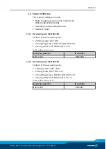
3.2.2 Determining the permissible transport load with NSR-A 160

Missing information or specifications can be requested from the
manufacturer.
Maximum permissible torque for NSR-A 160: 

 M

xy


= 600 Nm

Legend

M

Torque

Nm

F

Force

N

I

Effective lever length from the coupling interface between the
changeover head and pallet adapter to the center of gravity of the load.

m

m

Mass

kg

g

Acceleration due to gravity

m / s

2

m

total

m

 pallet adapter

 + m

 clamping pallet

 + m

 transport load

kg

a

Maximum acceleration of robot arm

m / s

2

Determination of formula values:

m

 pallet adapter, type: PKL 160 (aluminum)

 = 1.5 kg

m

 clamping pallet, type: PAL A 399 x 399 (aluminum)

 = 11 kg

m

 Transport load

 = 200 kg (example value)

I = 220 mm = 0.22 m (example value)

Calculating the acceleration force:

Summary of Contents for NSR-A 100

Page 1: ...Translation of Original Operating Manual Assembly and Operating Manual NSR A Pallet Changing System ...

Page 2: ...rations for the purpose of technical improvement Document number 389722 Version 06 00 29 07 2019 en SCHUNK GmbH Co KG All rights reserved Dear Customer thank you for trusting our products and our family owned company the leading technology supplier of robots and production machines Our team is always available to answer any questions on this product and other solutions Ask us questions and challen...

Page 3: ...ing conditions 10 2 6 Personnel qualification 10 2 7 Personal protective equipment 11 2 8 Organizational measures 11 2 9 Notes on safe operation 12 2 9 1 Handling 12 2 9 2 Holding force and screw strength 13 2 10 Transport 13 2 11 Malfunctions 13 2 12 Disposal 14 2 13 Fundamental dangers 14 2 13 1 Protection during handling and assembly 14 2 13 2 Protection during commissioning and operation 15 2 ...

Page 4: ... NSR A 160 46 5 5 Screw tightening torques 47 5 5 1 Screw tightening torques for NSR A 100 47 5 5 2 Screw tightening torques for NSR A 160 47 5 6 Tolerances and installation conditions for clamping pins in customer specific pallet adapters 48 5 6 1 Installation condition for clamping pin for NSR A 100 49 5 6 2 Installation condition for clamping pin for NSR A 160 50 5 7 Installing the sensors 51 5...

Page 5: ...s manual Illustrations in this manual are provided for basic understanding and may differ from the actual product design In addition to these instructions the documents listed under Applicable documents 6 are applicable 1 1 1 Presentation of Warning Labels To make risks clear the following signal words and symbols are used for safety notes DANGER Danger for persons Non observance will inevitably c...

Page 6: ...sizes NSR A 100 NSR A 160 1 2 Warranty If the product is used as intended the warranty is valid for 24 months from the ex works delivery date under the following conditions Observe the applicable documents Applicable documents 6 Observe the ambient conditions and operating conditions Observe the maximum number of clamping cycles Technical data 18 Observance of the specified care and maintenance in...

Page 7: ...nt of the accessory pack 2 fitting screws 8f7 M6 3 mounting screws M6 x 25 DIN 912 12 9 2 O rings DIN 3771 NBR 10 Ø 3 x 1 5 ID No of the accessory pack Accessory pack for ID number NSR A 100 9987230 1 3 2 Accessory pack for NSR 160 Content of the accessory pack 1 fitting screws 10f7 M8 1 fitting screw 10f7 M8 x 45 3 mounting screws M8 x45 DIN 912 12 9 2 O rings DIN 3771 NBR 70 Ø 4 5 x 1 5 ID No of...

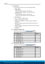
Page 8: ...mping pin Adapter plates for fastening the pneumatic or electrical feed through modules Sealing kit 1 4 1 Sealing kit for NSR A 100 Position of the item numbers Assembly drawings 59 Wearing parts we recommend replacing when maintenance is performed Item Designation Quantity 20 O ring Ø 4 5 x 1 4 21 O ring Ø 11 x 1 4 22 Sealing element 1 23 O ring Ø 20 x 1 5 2 25 O ring Ø 2 5 x 1 2 27 O ring Ø 64 x...

Page 9: ...pallets is not being used as intended if for example it is used for turning applications without consulting SCHUNK it is used in working environments that are not permissible people are working on machines or technical equipment that do not comply with the EC Machinery Directive 2006 42 EC disregarding the applicable safety regulations and the technical data specified by the manufacturer are excee...

Page 10: ...qualified personnel Before working with the product the personnel must have read and understood the complete assembly and operating manual Observe the national safety regulations and rules and general safety instructions The following personal qualifications are necessary for the various activities related to the product Trained electrician Due to their technical training knowledge and experience ...

Page 11: ...eying the rules The operator must employ suitable organizational measures and instructions in order to ensure that the relevant safety rules are obeyed by the persons asked to operate maintain and repair the product Checking the behavior of personnel The operator must at least occasionally check that the personnel are behaving in a safety conscious manner and are aware of the potential hazards Dan...

Page 12: ...e connection is not offset Check the approach position of the pallet handling at regular intervals The position of the handling system can change slightly particularly with high loading weights or when the clamping pallet is bearing the loading weight significantly towards the front In the event of eccentricity on the coupling interfaces the relevant traveling axes of the handling system must be a...

Page 13: ...mer specific devices a sufficiently dimensioned pallet adapter or a sufficiently thick mounting material is provided 2 10 Transport Handling during transport Incorrect handling during transport may impair the product s safety and cause serious injuries and considerable material damage When handling heavy weights use lifting equipment to lift the product and transport it by appropriate means Secure...

Page 14: ...he system If the energy supply is connected do not move any parts by hand Do not reach into the open mechanism or movement area of the product during operation 2 13 1 Protection during handling and assembly Incorrect handling and assembly Incorrect handling and assembly may impair the product s safety and cause serious injuries and considerable material damage Have all work carried out by appropri...

Page 15: ... material damage human access to the movement range of the machine must be restricted Limit prevent accidental access for people in this area due through technical safety measures The protective cover and protective fence must be rigid enough to withstand the maximum possible movement energy EMERGENCY STOP switches must be easily and quickly accessible Before starting up the machine or automated s...

Page 16: ...amping pallet connected WARNING Risk of injury to operating personnel due to movement of robot arm Uncontrolled movements during the setup of the pallet changing system and during operation may cause severe injury During setup of the pallet changing system accidental actuation of the robot arm must be prevented by means of suitable countermeasures Ensure that the machines and equipment fulfill the...

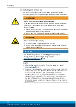
Page 17: ...lipping sources and can cause falls Ensure that the working environment is clean before starting assembly and installation work Wear suitable safety boots Follow the safety and accident prevention regulations when operating the pallet changing system especially when working with machine tools and other technical equipment CAUTION Risk of burns due to workpieces with high temperatures Wear protecti...

Page 18: ...upport on the module flat surface The directions of force for the maximum permissible torque are shown in the illustration in the Coupling Interface chapter Coupling interface for NSR A 100 and NSR A 160 31 2 Alternatively the clamping pin can be screwed to the pallet or device using an M6 screw In this case ensure that the maximum bending moments are reduced to 50 Nm An M8 screw is the preferable...

Page 19: ... the emergency stop switch is actuated Inclusion of the acceleration values is of crucial importance for the operational safety of the pallet changing system and the entire robot and palletizing system If it is not taken into account it can result in accidents and damage to the whole system 3 2 1 Determining the permissible transport load with NSR A 100 Missing information or specifications can be...

Page 20: ...ulating the acceleration force Maximum permissible moment load Mxy for NSR A 100 Mxy 75 Nm Result of calculation Taking into account the robot acceleration the loading weight obtained in the calculation example is permissible A higher loading weight requires a shortening of the effective lever length from the coupling interface to the center of gravity of the load or a reduction in the robot accel...

Page 21: ... lever length from the coupling interface between the changeover head and pallet adapter to the center of gravity of the load m m Mass kg g Acceleration due to gravity m s2 mtotal mpallet adapter mclamping pallet mtransport load kg a Maximum acceleration of robot arm m s2 Determination of formula values mpallet adapter type PKL 160 aluminum 1 5 kg mclamping pallet type PAL A 399 x 399 aluminum 11 ...

Page 22: ...g into account the robot acceleration the loading weight obtained in the calculation example is permissible A higher loading weight requires a shortening of the effective lever length from the coupling interface to the center of gravity of the load or a reduction in the robot acceleration For every change to the technical data a calculation must be performed ...

Page 23: ...amping pin 2 The changeover head mounted to the robot couples the pallet adapter which is mounted on the customer s clamping pallets In the changeover head a pneumatically driven locking piston creates a secure form fit connection to the clamping pin Monitoring the system state with sensors The pallet changing system NSR A is prepared for monitoring the system state Monitoring pallet change system...

Page 24: ...ated pallet loading The pallet changing system with the handling system is the interface between the machine work area and pallet rack Robots Robot flange Changeover head NSR A Pallet adapter PKL Clamping pallet Module for stationary use application Machine table Application example for automated pallet loading ...

Page 25: ...apting the clamping pallet Clamping pin Mounting stud for torsion resistance Only DIN EN ISO 4762 12 9 M8 mounting screws permissible Bore holes for fastening with lag screws M6 Pallet adapter PKL 100 0 Two long cylindrical screws act as lag screws and guarantee a high holding force and rigidity with heavy loading weights The connection interface between the clamping pallet and pallet adapter is s...

Page 26: ...ription 26 06 00 NSR A Assembly and Operating Manual en 389722 Clamping pin NSR SPA 100 Lag screw Only DIN EN ISO 4762 12 9 M8 mounting screws permissible Mounting surface of clamping pallet Pallet adapter PKL 100 90 ...

Page 27: ...Design and Description 06 00 NSR A Assembly and Operating Manual en 389722 27 Mounting surface of clamping pallet Connection interface between the clamping pallet and pallet adapter ...

Page 28: ...ter has a locating surface and four mounting screws for adapting the clamping pallet Alternatively the clamping pallets can be attached with two lag screws Clamping pin Mounting stud for torsion resistance Only DIN EN ISO 4762 12 9 M16 mounting screws permissible Bore holes for fastening with lag screws M8 Pallet adapter PKL 160 0 Two long cylindrical screws act as lag screws and guarantee a high ...

Page 29: ...iption 06 00 NSR A Assembly and Operating Manual en 389722 29 Clamping pin SPA 440 16RF Lag screw Only DIN EN ISO 4762 12 9 M16 mounting screws permissible Mounting surface of clamping pallet Pallet adapter PKL 160 90 ...

Page 30: ...Design and Description 30 06 00 NSR A Assembly and Operating Manual en 389722 Mounting surface of clamping pallet Connection interface between the clamping pallet and pallet adapter ...

Page 31: ...t adapter PKL 90 Mounting stud Mounting stud Torsion resistance for pallet adapter PKL 0 and PKL 90 without adapter plate NOTE Only an original SCHUNK clamping pin may be used on the coupling interface with the designated mounting screws Check the screw fitting of the clamping pin at regular intervals to ensure that it is secure Observe the tightening torque Screw tightening torques 47 The pallet ...

Page 32: ...d the relevant side of the piston must be able to ventilate When disconnecting hose lines the relevant openings must be secured with seal plugs to prevent ingress of dirt or cooling lubricant Observe tolerances when linking pallet changing systems If there is a coupling interface of 2 linked pallet changing systems make sure that the flatness and height deviation of the locating surfaces between t...

Page 33: ...g the pallet changing system during transport Transport with care Use a crane and or a trolley for transporting the system Wear personal protective equipment CAUTION Risk of injury due to sharp edges and rough or slippery surfaces Wear personal protective equipment particularly protective gloves Ø Carefully lift the pallet changing system out of the packaging with suitable lifting equipment Ø Chec...

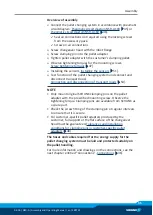
Page 34: ...due to crushing Install the pallet changing system with care Do not place any limbs into the gap or between the clamping pallets and the machine CAUTION Material damage due to incorrect tightening torques During assembly observe tightening torques Screw tightening torques 47 NOTE Observe the requirements for the compressed air supply Technical data 18 In case of compressed air loss cutting off the...

Page 35: ...nging system and connect and disconnect transport load Connection and disconnection of transport loads 54 NOTE Only mount original SCHUNK clamping pins on the pallet adapter with the prescribed mounting screw Observe the tightening torque Clamping pins are available from SCHUNK as a spare part Check the screw fitting of the clamping pin at regular intervals to ensure that it is secure For customer...

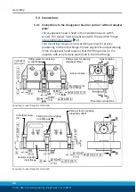
Page 36: ...on the robot flange Precise alignment and positioning of the changeover head requires that the fitting bores on the opposite side are precisely positioned in the robot flange Mounting to the robot flange Cylindrical screw x3 Fitting screw for centering in middle axis Fitting screw for aligning diagonally offset Pneumatic connections Sensor cables Sensor cables Mounting to robot flange for NSR A 10...

Page 37: ...connection Locked connection on base side M5 thread Mounting groove locked monitoring prepared for magnetic switch MMS 22 SA Mounting groove unlocked monitoring prepared for magnetic switch MMS 22 SA M5 thread for adapter attachment M5 thread for adapter attachment Unlocking connection M5 Air purge connection with cleaning function M5 Locked connection M5 Air outlets for cleaning function Fixing b...

Page 38: ... with cleaning function M5 Air outlets for cleaning function Locked connection M5 Locating surfaces for pallet adapter Fitting screws for positional orientation Unlocking connection M5 Torsion resistance using mold inclines on both sides Torsion resistance using fitted bushings Fixing bore for M8 cylindrical screw 5x Mounting groove monitoring open for sensor MMS 22 SA M5 thread Air outlets for cl...

Page 39: ...n the hose free direct connections on the base side must each be sealed with an O ring In the customer specific attachment flange recessed O ring seats are required for this Machine the axial sealing O ring seat according to the following dimensions Ø 5 5 0 1 x 0 7 0 05 The accessory pack contains O rings see Assembly drawing item 19 for sealing the bottom hose free direct connections When the loc...

Page 40: ... the robot flange Cylindrical screw x3 Fitting screw for centering in middle axis Fitting screw for aligning diagonally offset Pneumatic connections Sensor cable Mounting to robot flange with adapter plate for pneumatic or electrical feed through modules for NSR A 100 Customer specific robot flange Cylindrical screw 3x Fitting screw for aligning in middle axis Fitting screw for aligning diagonally...

Page 41: ...used to ensure torsion resistance Air outlets for cleaning function Air outlets for cleaning function Locked connection M5 Air purge connection with cleaning function M5 Air purge connection with cleaning function M5 Unlocking connection M5 Locating surface for pallet adapter Fixing bore for cylindrical screw M6 3x Air outlets for cleaning function Mounting thread pallet presence monitoring prepar...

Page 42: ...utlets for cleaning function Locked connection M5 Locating surfaces for pallet adapter Fitting screws for positional orientation Unlocking connection M5 Torsion resistance using fitted bushings Fixing bore for cylindrical screw M6 3x Mounting groove monitoring open for sensor MMS 22 SA M5 thread Air outlets for cleaning function Air purge connection with cleaning function M5 Torsion resistance usi...

Page 43: ...y drawings 59 5 4 4 Locked connection The pallet changing system has a locked connection When compressed air is applied it supports the spring actuated locking procedure actively with air pressure to increase the pull in force even further In the dynamic work process switching on the locked connection is always recommended There is the option of controlling the pallet changing system either via th...

Page 44: ...the open air connection must be sealed with a M5 locking screw see chapter Assembly Drawings Assembly drawings 59 It is advisable to use the air purge function if the changeover head approaches the pallet adapter In doing so the two system components to be coupled are cleaned of dirt and chips When actuating the pallet changing system observe the following Maximum pressure of the air purge 6 bar T...

Page 45: ... center position ventilated Pneumatic circuit symbols 3 2 directional control valve Pressure switch Pressure gauge Flow control valve Compressed air supply Pneumatic circuit diagram with adapter plate Unlocking connection Locked connection Blow out air max 6 bar Actuation using 6 bar also on base side via hose free direct connections 5 3 directional control valve center position ventilated Pneumat...

Page 46: ... ventilated Pneumatic circuit symbols 3 2 directional control valve Pressure switch Pressure gauge Flow control valve Compressed air supply Exhaust air Pneumatic circuit diagram with adapter plate Unlocking connection Locked connection Blow out air max 6 bar Actuation using 6 bar also on base side via hose free direct connections 5 3 directional control valve center position ventilated Pneumatic c...

Page 47: ...12 9 M6 15 3 Clamping pin pallet adapter 12 9 M8 32 4 Countersunk screws Pallet adapter clamping pallet 10 9 M6 13 Alternative attachment option Technical data 18 5 5 2 Screw tightening torques for NSR A 160 Item Mounting Strength class Thread Tightening torque Nm 1 Quick change head robot flange 12 9 M8 32 2 Lag screws Pallet adapter clamping pallet 10 9 M8 28 3 Clamping pin pallet adapter 12 9 M...

Page 48: ...all the clamping pin with a screw of strength class 12 9 It is imperative that the tightening torque is strictly adhered to Screw tightening torques 47 If the clamping pin is to be used in customer specific pallet adapters the customer must provide a sufficiently dimensioned depth of engagement in the clamping pin or a sufficiently thick mounting material in the adapter strip The installation dime...

Page 49: ...on condition for clamping pin for NSR A 100 Screw Steel Aluminum Customer specific pallet or device Tolerances and installation conditions for clamping pins when installing in a customer specific pallet adapter A B C D E 8 13 M8 9 11 Alternative attachment option Technical data 18 ...

Page 50: ... clamping pins when installing in a customer specific pallet adapter A B C D E F 13 16 M16 16 16 20 Note If the clamping pin is installed in an aluminum adapter strip it is essential to install a steel washer under the screw head of the cylindrical screw DIN EN 4762 M16 12 9 The steel washer can be ordered from SCHUNK Alternative attachment option Technical data 18 ...

Page 51: ...t and Overview of compatible sensors 51 For technical data for the suitable sensors see assembly and operating manual and catalog datasheet The assembly and operating manual and catalog datasheet are included in the scope of delivery for the sensors and are available at schunk com Information on handling sensors is available at schunk com or from SCHUNK contact persons 5 7 1 Overview of compatible...

Page 52: ...e sensor using the set screw Tightening torque 10 Ncm Ø Adjust sensor see Sensor Assembly and Operating Manual Ø Query unlocked position and test functionality Query pallet change system locked Ø Clamp the pallet to be clamped Ø Slide sensor 2 to the stop in the short groove y The sensor switches Ø Pull the sensor 2 back again slowly until it reaches the switching position but still switches Ø Sec...

Page 53: ...et screw 33 Ø Screw in sensor 2 Ø Set switching point so that the proximity switch switches when the pallet is present Ø Secure sensor using the counter nut 3 Ø Adjust sensor see Sensor Assembly and Operating Manual Ø Query clamping pin present position and test functionality NOTE The switching point of the proximity switch must be set so that the signal that the clamping pin has been detected onl...

Page 54: ...ion of transport loads Approach the coupling interface between changeover head and clamping pin in the pallet adapter in advance with no tilt angle and eccentricity Check that the traverse path is collision free through the entire machining area Work at a reduced travel speed when loading Ensure a correctly aligned traverse path for connecting and disconnecting the clamping pallet The loading hand...

Page 55: ...per Position clamping pallet on module for stationary use application or remove from module for stationary use application Traverse path of movement axes when loading Connect or release the clamping pallet Robot module in unlocked coupling process Connect blast air cleaning function during loading Automated connection and disconnection of transport loads ...

Page 56: ...5 bar A component is broken e g due to overloading Replace the module or send it to SCHUNK for repair Excess tensile load on clamping pins Reduce support weight The clamping area does not unlock properly Possible cause Remedial measures Pressure below minimum Check operating pressure min 5 bar Hose diameter below minimum For required hose diameters see chapter General Assembly Notes The locked con...

Page 57: ...nly have the cover removed by trained specialist personnel In cases of doubt send the pallet change system to SCHUNK for repair 7 1 Maintenance intervals Maintenance interval Clamping cycles for NSR A 100 160 Maintenance work 1000 or after 2 weeks Check functionality of the pallet changing system Information on error free function 58 50 000 Carry out visual inspection and check for leaks Carry out...

Page 58: ...des move smoothly at minimum system pressure 5 bar 7 3 Carry out visual inspection and check for leaks Visual inspection Inspect the pallet changing system for possible damage and wear After a collision e g when connecting or disconnecting the transport load carry out a visual inspection for possible damage to the components e g cracks If damage or signs of malfunctions are identifiable on the pal...

Page 59: ...Maintenance 06 00 NSR A Assembly and Operating Manual en 389722 59 7 4 Assembly drawings 7 4 1 Assembly drawings NSR A 100 ...

Page 60: ...Maintenance 60 06 00 NSR A Assembly and Operating Manual en 389722 Without adapter plate Sensor system is available to order separately as an accessory Components are inseparably joined ...

Page 61: ...Maintenance 06 00 NSR A Assembly and Operating Manual en 389722 61 Adapter plate Sensor system is available to order separately as an accessory Components are inseparably joined ...

Page 62: ...Maintenance 62 06 00 NSR A Assembly and Operating Manual en 389722 7 4 2 Assembly drawings NSR A 160 ...

Page 63: ...Maintenance 06 00 NSR A Assembly and Operating Manual en 389722 63 Without adapter plate ...

Page 64: ...Maintenance 64 06 00 NSR A Assembly and Operating Manual en 389722 Adapter plate Sensor system is available to order separately as an accessory Components are inseparably joined ...

Page 65: ...conformity of the machine into which the partly completed machine is to be installed with the provisions of the Machinery Directive 2006 42 EC is confirmed Applied harmonized standards especially EN ISO 12100 2010 Safety of machinery General principles for design Risk assessment and risk reduction EN ISO 4414 2010 Hydraulic fluid power General rules and safety requirements for pneumatic systems an...

Page 66: ... 1 1 1 Definitions X 1 1 2 Principles of safety integration X 1 1 3 Materials and products X 1 1 4 Lighting X 1 1 5 Design of machinery to facilitate its handling X 1 1 6 Ergonomics X 1 1 7 Operating positions X 1 1 8 Seating X 1 2 Control Systems 1 2 1 Safety and reliability of control systems X 1 2 2 Control devices X 1 2 3 Starting X 1 2 4 Stopping X 1 2 4 1 Normal stop X 1 2 4 2 Operational st...

Page 67: ...ble guards X 1 4 2 3 Adjustable guards restricting access X 1 4 3 Special requirements for protective devices X 1 5 Risks due to other hazards 1 5 1 Electricity supply X 1 5 2 Static electricity X 1 5 3 Energy supply other than electricity X 1 5 4 Errors of fitting X 1 5 5 Extreme temperatures X 1 45 6 Fire X 1 5 7 Explosion X 1 5 8 Noise X 1 5 9 Vibrations X 1 5 10 Radiation X 1 5 11 External rad...

Page 68: ...quirements for certain categories of machinery X 2 1 Foodstuffs machinery and machinery for cosmetics or pharmaceutical products X 2 2 Portable hand held and or guided machinery X 2 2 1 Portable fixing and other impact machinery X 2 3 Machinery for working wood and material with similar physical characteristics X 3 Supplementary essential health and safety requirements to offset hazards due to the...

Reviews: