background image

Assembly

14.00 | JGP | Assembly and Operating Manual | en | 389157

41

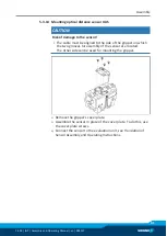
5.3.14 Mounting optical distance sensor OAS

CAUTION

Risk of damage to the sensor!

The cable must be aligned to the side of the gripper on which
the two grooves for assembly of the sensor are located. 
The other side can be used for mounting the gripper.

Ø

Remove the gripper's cover plate.

Ø

Assemble the sensor in place of the cover plate. To do this, use
the cover plate screws.

Ø

Connect the sensor to the evaluation unit, see Translation of
Sensor Assembly and Operating Instructions.

Summary of Contents for JGP

Page 1: ...Translation of the original manual Assembly and Operating Manual JGP 2 Finger Parallel Gripper...

Page 2: ...tions for the purpose of technical improvement Document number 389157 Version 14 00 27 08 2019 en SCHUNK GmbH Co KG All rights reserved Dear Customer thank you for trusting our products and our family...

Page 3: ...Gripper fingers 10 2 6 Ambient conditions and operating conditions 10 2 7 Personnel qualification 11 2 8 Personal protective equipment 12 2 9 Notes on safe operation 12 2 10 Transport 13 2 11 Malfunc...

Page 4: ...tion sensor FPS 37 5 3 12 Mounting analog position sensor APS M1 38 5 3 13 Mounting analog position sensor APS Z80 39 5 3 14 Mounting optical distance sensor OAS 41 5 3 15 Mounting the radio system RS...

Page 5: ...r basic understanding and may differ from the actual product design In addition to these instructions the documents listed under Applicable documents 6 are applicable 1 1 1 Presentation of Warning Lab...

Page 6: ...P 125 JGP 160 JGP 200 JGP 240 JGP 300 1 1 5 Variants This operating manual applies to the following variations JGP without gripping force maintenance JGP with gripping force maintenance O D gripping A...

Page 7: ...essory pack 1 3 1 Accessories kit Content of the accessory pack 6 x Centering sleeves for mounting 2 x O ring for hose free direct connection 2 x screw plug for hose connection ID No of the accessory...

Page 8: ...accessory articles can be used with the corresponding product variants see catalog data sheet 1 4 1 Seal kit ID No of the seal kit Seal kit for JGP JGP 40 5516793 JGP 50 0370891 JGP 64 0370892 JGP 80...

Page 9: ...in a machine system The applicable guidelines must be observed and complied with The product is intended for industrial and industry oriented use Appropriate use of the product includes compliance wit...

Page 10: ...in a way that the product reaches either the position open or closed in a de energized state Only exchange the gripper fingers when no residual energy remains in the product Make sure that the produc...

Page 11: ...lated to the product Trained electrician Due to their technical training knowledge and experience trained electricians are able to work on electrical systems recognize and avoid possible dangers and k...

Page 12: ...les when handling hazardous substances Wear close fitting protective clothing and also wear long hair in a hairnet when dealing with moving components 2 9 Notes on safe operation Incorrect handling of...

Page 13: ...or in case of malfunctions Immediately remove the product from operation and report the malfunction to the responsible departments persons Order appropriately trained personnel to rectify the malfunct...

Page 14: ...e product s safety and cause serious injuries and considerable material damage Have all work carried out by appropriately qualified personnel For all work secure the product against accidental operati...

Page 15: ...through technical safety measures The protective cover and protective fence must be rigid enough to withstand the maximum possible movement energy EMERGENCY STOP switches must be easily and quickly ac...

Page 16: ...measures to secure the danger zone WARNING Risk of injury due to unexpected movements If the power supply is switched on or residual energy remains in the system components can move unexpectedly and...

Page 17: ...nexpectedly and cause serious injuries Disassemble the product cautiously Make sure that no residual energy remains in the system WARNING Risk of injury from objects falling during energy supply failu...

Page 18: ...force maintenance with gripping force maintenance 8 6 5 Pressure range for air purge bar 0 5 1 More technical data is included in the catalog data sheet Whichever is the latest version Environmental...

Page 19: ...d Operating Manual en 389157 19 4 Design and description 4 1 Design 2 Finger Parallel Gripper 1 Housing 2 Air purge connection 3 Compressed air main connection 4 Base jaw 4 2 Description Universal 2 f...

Page 20: ...eduction and or damping Observe the diagrams and information in the catalog data sheet NOTE Observe the requirements for the compressed air supply Technical Data 18 In case of compressed air loss cutt...

Page 21: ...ecessary strength class When mounting from the rear or at the side use cylindrical pins for fixing the product in place Secure the gripper fingers to the base jaws Mechanical connection 21 Use centeri...

Page 22: ...eeve 4 5 6 8 10 2 Thread in base jaws M2 5 M3 M4 M5 M6 Mounting screw strength class 12 9 Max depth of engagement from locating surface mm 6 1 8 5 10 10 14 Item Mounting JGP 125 160 200 240 300 1 Cent...

Page 23: ...urface mm for variants IS AS 6 9 11 16 12 18 15 18 14 16 20 20 2 Centering sleeve 5 6 8 8 10 12 6 Fitting bore for centering pin mm 4H7 4H7 5H7 6H7 Side B 4 Mounting screw M2 5 M3 M4 M4 M5 M6 Mounting...

Page 24: ...20 25 5 23 31 31 2 Centering sleeve 12 14 16 22 6 Fitting bore for centering pin mm 6H7 10H7 Side B 4 Mounting screw M6 M8 M10 M12 Mounting screw according to standard DIN EN ISO 4762 2 Centering sle...

Page 25: ...onnection 4 Air purge connection Hose free direct connection 5 O ring 6 Attachment 7 Product Thread diameter of the air connections Item 40 50 64 80 100 125 160 200 240 300 1 2 x M3 2 x M5 2 x M5 2 x...

Page 26: ...hunk com Information on handling sensors is available at schunk com or from SCHUNK contact persons 5 3 1 Overview of sensors Designation JGP 40 50 64 80 100 125 160 200 240 300 Magnetic switch MMS 22...

Page 27: ...S 23 9 100 IS 53 7 50 15 4 125 23 0 50 AS 20 8 125 AS 59 6 50 IS 31 4 125 IS 52 9 64 22 4 160 31 4 64 AS 19 2 160 AS 71 9 64 IS 40 4 160 IS 71 4 80 26 0 80 AS 22 4 80 IS 44 0 NOTE The magnetic switch...

Page 28: ...r jaw X 10 mm 10 of the nominal stroke per jaw Example Product with 7 mm nominal stroke per jaw 7 mm 20 1 4 mm 5 3 4 Turn control cam Turn control cam example control cam for inductive monitoring Depe...

Page 29: ...d of the groove Pull the sensor 1 1 back again slowly until it switches Secure the sensor 1 1 using the set screw 4 Tightening torque 10 Ncm Bring product into the Gripper open or Part gripped positio...

Page 30: ...dimension l1 In Optimal Mode the sensor identifies the optimal position in the groove itself SCHUNK recommends Optimal Mode for setting the sensors Setting the sensor in Optimum mode Bring gripper in...

Page 31: ...r 2 NOTE If there is no T nut available slide the sensor according to dimension I1 into the groove 2 Setting dimensions for magnetic switches 27 5 3 7 Mounting programmable magnetic switch MMS 22 PI2...

Page 32: ...ly Observe the maximal tightening torque NOTE If there is no T nut available slide the sensor according to dimension I1 into the groove 2 Setting dimensions for magnetic switches 27 Turn the sensor 1...

Page 33: ...the sensor 1 1 into the bracket 2 until it stops Tighten the screw 3 on the bracket 2 Tightening torque 0 2 Nm Open gripper or grip part Unfasten the screw 4 Turn the screw 5 to adjust the position of...

Page 34: ...cam 6 outwards until the sensor 2 1 no longer responds Move the control cam 6 back towards the inside until the sensor 2 1 begins to switch Tighten screw 4 while pressing the control cam in the direct...

Page 35: ...sor 1 1 into the bracket 2 until it stops Tighten the screw 3 on the bracket 2 Tightening torque 0 2 Nm Open gripper or grip part Unfasten the screw 4 Turn the screw 5 to adjust the position of the co...

Page 36: ...cam 6 outwards until the sensor 2 1 no longer responds Move the control cam 6 back towards the inside until the sensor 2 1 begins to switch Tighten screw 4 while pressing the control cam in the direct...

Page 37: ...he maximal tightening torque Move product to the gripper open position Loosen screw 4 and remove control cam 6 for the inductive monitoring from the base jaw Remove screw 5 from the base jaw Slide con...

Page 38: ...pen position Loosen screw 4 and remove control cam 6 for the inductive monitoring from the base jaw Apply adhesive to the top and sides of the control cam 6 from the mounting kit Make sure that there...

Page 39: ...tilt in the guide if it was not fixed exactly in the base jaw Apply the switching cam in the direction of the base jaw so that the cam does not contact the housing of the gripper During the monitoring...

Page 40: ...hich comes into contact with the sensor SCHUNK recommends the adhesive Loctite 290 or 638 Slide control cam 6 into the base jaw to the stop Ensure that the higher front side of the control cam 6 is po...

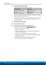
Page 41: ...d to the side of the gripper on which the two grooves for assembly of the sensor are located The other side can be used for mounting the gripper Remove the gripper s cover plate Assemble the sensor in...

Page 42: ...ly and operating manual for the radio system 5 3 16 Mounting force measuring jaw FMS Screw intermediate jaws 2 onto the base jaws 4 Use centering sleeves between base jaw and intermediate jaw Screw pa...

Page 43: ...ce component or send it to SCHUNK for repair 6 2 Product is not executing the complete stroke Possible cause Corrective action Dirt deposits between cover and piston Clean and if necessary re lubricat...

Page 44: ...alled optimally If present Open the flow control couplings on the product to the maximum that the movement of the jaws occurs without bouncing and hitting Check compressed air lines Inner diameters of...

Page 45: ...refore we recommend to have the module serviced and the seals replaced by SCHUNK If this is not possible you can carry out the maintenance and replace the seals yourself 7 2 Maintenance intervals CAUT...

Page 46: ...ricated as needed Remove the set screw of the air purge connection and replace it with a lubrication nipple 7 4 Disassembly and assembly 7 4 1 Disassemble the product 7 4 1 1 Variant without maintenan...

Page 47: ...g forces The cover housing is spring tensioned Carefully disassemble the product Clamp the gripper between the base jaws 2 and the cover 9 in the vise so that you can still remove the 4 screws 46 Unsc...

Page 48: ...ing forces The cover is under spring tension Carefully disassemble the product Remove the compressed air hoses Remove the cover 5 Mark the installation position of the piston 3 and the base jaws 2 in...

Page 49: ...nce of gripping force AS Sizes 40 100 assemble cylinder piston using an assembly device Assembly with assembly device 50 Size 125 assemble in the reverse order without assembly device Sizes 160 300 as...

Page 50: ...3 in the housing 50 Put the cylinder piston 10 with the sealing 30 and the spring force 25 in the housing 50 Carefully put device 100 over the cylinder piston 60 and attach to the housing 50 using the...

Page 51: ...25 distance bolts 11 and the cylinder piston 10 with the seal 30 in the housing 50 Carefully put device 1 103 over the cylinder piston 10 and attach to the housing 50 using the screws 1 102 Put on de...

Page 52: ...linder piston assembly device dimensions in mm a b c d e l1 l2 d1 d2 d3 t1 t2 t3 JGP 40 38 24 20 22 5 14 5 32 18 5 3 5 6 5 14 2 4 JGP 50 42 30 25 25 19 35 22 6 3 5 8 18 2 5 6 JGP 64 52 36 27 31 24 42...

Page 53: ...5 15 9 12 JGP 200 154 100 65 110 9 20 78 18 11 14 JGP 240 186 115 80 125 11 22 88 20 13 5 16 JGP 300 210 140 95 149 11 30 114 3 26 17 5 22 Cylinder piston assembly device dimensions in mm Size d8 d9 l...

Page 54: ...0 JGP 300 40 2 2 Nm 2 2 Nm 5 9 Nm 10 Nm 10 Nm 24 Nm 47 Nm 75 Nm 75 Nm 120 Nm 41 0 73 Nm 1 3 Nm 1 3 Nm 3 Nm 3 Nm 6 Nm 6 Nm 6 Nm 6 Nm 6 Nm 45 2 2 Nm 2 2 Nm 10 Nm 17 Nm 17 Nm 41 Nm 83 Nm 116 Nm 116 Nm 15...

Page 55: ...ng force maintenance 1 Wearing part replace during maintenance Included in the seal kit Seal kit can only be ordered completely 2 Positions are adapted to each other and can not be replaced by the cus...

Page 56: ...inger Parallel Gripper JGP pneumatic ID number 0308600 0308802 The partly completed machine may not be put into operation until conformity of the machine into which the partly completed machine is to...

Page 57: ...ments 1 1 1 Definitions X 1 1 2 Principles of safety integration X 1 1 3 Materials and products X 1 1 4 Lighting X 1 1 5 Design of machinery to facilitate its handling X 1 1 6 Ergonomics X 1 1 7 Opera...

Page 58: ...2 2 Interlocking movable guards X 1 4 2 3 Adjustable guards restricting access X 1 4 3 Special requirements for protective devices X 1 5 Risks due to other hazards 1 5 1 Electricity supply X 1 5 2 Sta...

Page 59: ...irements for certain categories of machinery X 2 1 Foodstuffs machinery and machinery for cosmetics or pharmaceutical products X 2 2 Portable hand held and or guided machinery X 2 2 1 Portable fixing...

Page 60: ...Notes 60 14 00 JGP Assembly and Operating Manual en 389157 Notes...

Reviews: