Assembly
02.00 | GWB | Assembly and Operating Manual | en | 389122
23
4.1.2 Pneumatic connection
CAUTION
Damage to the gripper is possible!
If the maximum permissible finger weight or the permissible
mass moment of inertia of the fingers is exceeded, the gripper
can be damaged.
•
A jaw movement always has to be without jerks and bounce.
•
You must therefore implement sufficient reduction and/or
damping.
•
Observe the diagrams and information in the catalog data
sheet.
NOTE
• Observe the requirements for the compressed air supply,
18].
• In case of compressed air loss (cutting off the energy line), the
components lose their dynamic effects and do not remain in a
secure position. However, the use of a SDV-P pressure
maintenance valve is recommended in this case in order to
maintain the dynamic effect for some time. Product variants
are also offered with mechanical gripping force via springs,
which also ensure a minimum clamping force in the event of a
pressure drop.
•
Hose-free direct connection:
Optionally to ground or to front.
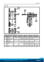
• Remove the M3 set-screws (21) from the selected direct
connections and close the lateral hose connections with the M5
locking screws supplied.
• Use the O-rings Ø 3 x 1.5 supplied in the accessory kit.
• Integrate the one-way flow control valves at a suitable place in
the gripper's pressure supply. Observe the circuit diagram in the
process (exhaust throttling).
CAUTION
Adjust the speed of the gripper using the one-way flow control
valves to allow the gripper to open and close smoothly without
jerking.


