System descriptionElectric gripper EGP withsafety functions
Page 1: ...System description Electric gripper EGP with safety functions ...
Page 2: ...t to make alterations for the purpose of technical improvement Document number 1381596 Version 01 00 14 01 2019 en SCHUNK GmbH Co KG All rights reserved Dear Customer thank you for trusting our products and our family owned company the leading techno logy supplier of robots and production machines Our team is always available to answer any questions on this product and other solutions Ask us quest...
Page 3: ... 6 3 Design and description 7 3 1 Example system setup Systemaufbau 7 3 2 Description 8 4 Functional description 9 4 1 Definition of the safe state of the gripper 9 4 2 Block diagram 10 4 3 Superordinate control system 10 4 4 Safety control system 11 4 5 Program sequence 12 5 Assembly and installation 13 5 1 Assembly 13 5 2 Commissioning 14 5 3 Commissioning checklist 15 6 Appendix 17 Wiring diagr...
Page 4: ...nt has to be prepared and applicable standards must be identified and applied In addition to these instructions the documents listed under Ap plicable documents 4 are applicable 1 2 Applicable documents Assembly and operating manual for gripper EGP Assembly and operating manual of the sensor IN 40 DGVU Certificate Certificate No MF 15008 DGVU Certificate Certificate No MF 17022 Secure control docu...
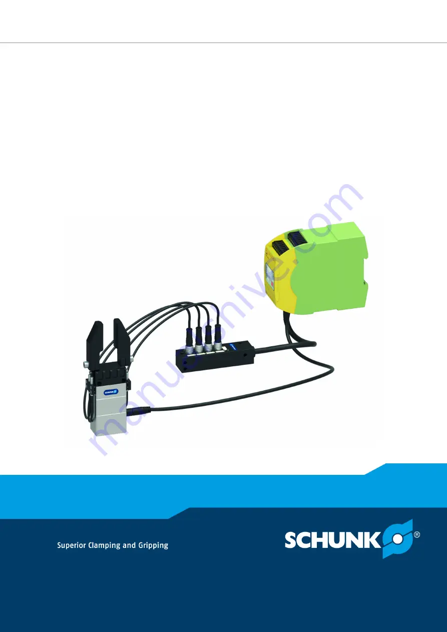
Page 5: ...commends inductive proximity switches IN 40 The following components are required for the system setup Electric gripper EGP 4 x sensors e g inductive proximity switches IN 40 S M8 SCHUNK Id No 0301474 Sensor bracket 2x SCHUNK Id No 9700901 Spacer sleeve for adjusting the sensor position SCHUNK Id No 5509536 Sensor distributor Safety control system e g PILZ PNOZmulti or LTI SMC1 Z10 ...
Page 6: ...1 00 Electric gripper EGP with safety functions System description en 1381596 2 Technical data Notes on the technical data are included in the respective document ation of the individual components Applicable documents 4 ...
Page 7: ... setup Systemaufbau Example system setup with safety control system 1 Sensor IN 40 4 Gripper power supply cable 2 Sensor distributor 5 gripper 3 Safety control system e g PILZ PNOZmulti 6 Sensor bracket Superordinate control system Gripper Superordinate control system Gripper Monitoring level Setup conventional left and with safety function right ...
Page 8: ...tion mode the functions of the monitoring level are active In released operation mode the functions are not active and haz ards may arise In released operation mode the customer must ensure that the plausibility of the sensor signals is monitored and evaluated The monitoring level comprises two safety functions and the eval uation logic Safe Operating Stop SOS Safe monitoring of the position of th...
Page 9: ... as soon as the position of the gripper fingers is undefined This is the case for example when a gripped workpiece is re moved by force application from the gripper during monitored op eration no release or the logical release signal low or Emergency Stop If a workpiece is removed the gripper fingers move until a signal change is made to one of the sensors overrun traverse If the configured grippi...
Page 10: ...perordinate control system It must be ensured that the connections are made for safety technology comply with the requirements of EN ISO 13849 1 When using a safe superordinate control system the sensor and evaluation logic that must be executed safely can be implemented in the superordinate control system In this case no additional control system is needed It must be ensured that the safety conne...
Page 11: ...te control system via the output signals Gripper Opened 1 Gripper Opened 2 Gripper Closed 1 and Gripper Closed 2 Processing of the sensor signals for further use in the customer specific application must be performed by the superordinate con trol system In maintenance mode and in emergency stop the safety control system carries out a plausibility check of the sensor signals In release mode the sen...
Page 12: ...cy stop low Enable edge high Reset edge high Confirm button high Reset confirm button edge high Diagram of state machine Each state transition is represented by an arrow in the direction of the new state If the transition condition is true the state trans ition occurs The application software has three basic behaviors Release mode Unchecked transmission of all signals from the gripper to the highe...
Page 13: ...ystem monitors its own power supply U 24 V 20 25 If the voltage exceeds or falls below the upper or lower voltage limit the power supply of the gripper is switched off and the safety control system must be restarted The sensors must be configured so that the overrun traverse of the gripper after a workpiece loss is short enough that there is no danger However the overrun traverse must be long enou...
Page 14: ...rements applicable to the end effector The forms and processes required for customer specific application must be observed For any modification of the customer specific application e g when gripping different workpieces the following points must be repeated Commissioning including adjustment of the sensors Risk assessment Documentation of commissioning If existing settings can be adopted e g if gr...
Page 15: ...fy the gripper I D gripping __________________________________________________ O D gripping __________________________________________________ Force fit gripping or form fit clamping ____________________________________ Gripping force adjustment _________________________________________ 5 Identify workpiece The workpiece to be gripped is uniquely identifiable Name Revision ________________________...
Page 16: ...tential Appropriate measures __________________________________________ ______________________________________________________________ 8 Identify ambient conditions Clean dry ______________________________________________ Ambient temperature C Cycles per minute _____________________________________________ 9 Assess risk and minimize if necessary Assess risk based on potential hazard e g crushing d...
Page 17: ...Appendix 01 00 Electric gripper EGP with safety functions System description en 1381596 17 6 Appendix Further information 2 Wiring diagram 1 Pilz 18 2 Wiring diagram 2 LTI 19 ...
Page 18: ...IHU JH IIQHW 6HQVRU UHLIHU JH IIQHW 6HQVRU UHLIHU JHVFKORVVHQ 6HQVRU 6LJQDO UHLIHU JHVFKORVVHQ 6LJQDO UHLIHU JH IIQHW UHLIHU JHVFKORVVHQ 6HQVRU 5 FNI KUXQJ UHLJDEH 5 FNI KUXQJ HKOHU JHVWULFKHOWH 2EMHNWH YRQ DQ EHUJHRUGQHWHU 6WHXHUXQJ 6LJQDO UHLIHU JHVFKORVVHQ 6LJQDO UHLIHU JH IIQHW UHLIHU 3 G 1U 1RW DOW UHLJDEH 5HVHW XVWLPPXQJ UHLIHU IIQHQ UHLIHU VFKOLH HQ 312 P 2 G 1U 6 LP 6FKDOWVFKUDQN DXIOHJHQ ...
Page 19: ...hließen gestrichelte Objekte von an übergeordneter Steuerung Not Halt 1 Freigabe 1 Not Halt 2 Freigabe 2 Zustimmung 1 Zustimmung 2 SPLC1 Safe PLC external X11 1 2 3 4 X12 1 2 3 4 X13 1 2 3 4 X14 1 2 3 4 4 3 2 X24 1 4 3 2 X23 1 4 3 2 X22 1 4 3 2 X21 1 X41 COM SafeIOExt1 Safe I O Extension external X11 1 2 3 4 X12 1 2 3 4 X13 1 2 3 4 X14 1 2 3 4 4 3 2 X24 1 4 3 2 X23 1 4 3 2 X22 1 4 3 2 X21 1 SCC IN...
Page 20: ...20 01 00 Electric gripper EGP with safety functions System description en 1381596 ...