


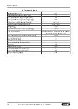


Assembly
22
06.00 | KTG | Assembly and operating manual | en | 389181
The inductive proximity switches are electronic components,
which can react sensitively to high-frequency interference or
electromagnetic fields.
• Check to make sure that the cable is fastened and installed
correctly. Provide for sufficient clearance to sources of high-
frequency interference and their supply cables.
• Parallel switching of several sensor outputs of the same type
(npn, pnp) is permissible, but does not increase the permissible
load current.
• Note that the leakage current of the individual sensors
(approx. 2 mA) is cumulative.
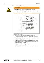
Assembly and adjustment
Proximity switch
1
"OPEN" proximity switch
4
Long switching lug
2
"CLOSED" proximity switch 5
Short switching lug
3
Clamping screw
6
Bracket for proximity
switch
1. Loosen the attachment screw (3) on the bracket.
2. Push the proximity switch (1/2) through the bore holes in the
bracket (6).
Observe a distance of 0.5 mm to the switching lug.
3. Secure the proximity switch by tightening the attachment
screw (3) (max. tightening torque of 1 Nm).
4. If necessary, adjust the switching lugs (4/5) so that the head of
the switching lug is above the center of the respective
proximity switch in the desired position of the base jaw.
5. To monitor intermediate positions, the long switching lug (5)
may have to be replaced with the M2 x 8 screw from the
accessory pack.
6. After correct adjustment, secure both switching lugs (4/5) with
a suitable adhesive.
Summary of Contents for 300275
Page 1: ...Original operating manual Assembly and operating manual KTG 2 finger parallel gripper...
Page 29: ......
Page 30: ......
Page 31: ......


