OPERATION
SRW1000 08/17
Operation Section 4-28
© 2017 Alamo Group Inc.
OPERA
T
ION
13. DISCONNECTING THE WINDROWER FROM THE TRACTOR
Before disconnecting the implement, the PTO must be disengaged and drum rotation at a complete stop. Move
the implement to a level storage location and lower the implement to the ground. If the implement is not resting
securely on the ground, block the implement up securely before attempting to disconnect it from the tractor.
Use extreme care to keep feet and hands out from under the implement and clear of any pinch points when
disconnecting the implement from the tractor.
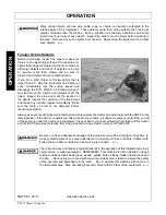
Never stand or allow another person to stand between a running Tractor and the Unit when
disconnecting the Implement from the Tractor 3-point hitch. Always shut the Tractor off
completely and set the parking brake before attempting to disconnect the Implement pins
from the Tractor hitch.
1. When disconnecting windrower the tractor
should be completely shut down and secured in
position. Relieve hydraulic pressure by moving
the control levers back and forth several times.
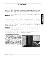
2. Lower the parking jack and raise the windrower
until the tongue clevis is no longer resting on
the tractor drawbar and is supported solely by
the jack. Make sure the jack foot is securely
resting at ground level or securely supported by
a block before raising the windrower.
3. Once the windrower tongue is being supported
entirely by the jack, remove the hitch bolt,
locknut, and washers.
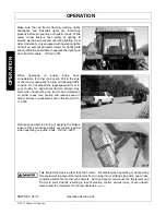
4. Remove the windrower driveline from the
tractor PTO shaft. Place the driveline in its
storage bracket to prevent it from contacting
mud or dirt which can contaminate the universal
joint bearings and shorten the life of the
driveline.
5. Remove the hydraulic hoses from the tractor
and secure to the windrower to prevent contact
with dirt.
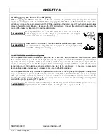
Always shut the Tractor completely down, place the transmission in park, and set the
parking brake before you or anyone else attempts to connect or disconnect the Implement
and Tractor hitches.
(S3PT-15)
Summary of Contents for SRW1000
Page 4: ......
Page 7: ...Safety Section 1 1 2017 Alamo Group Inc SAFETY SECTION ...
Page 19: ...SAFETY SRW1000 08 17 Safety Section 1 13 2017 Alamo Group Inc SAFETY Decal Location ...
Page 21: ...SAFETY SRW1000 08 17 Safety Section 1 15 2017 Alamo Group Inc SAFETY Decal Description ...
Page 22: ...SAFETY SRW1000 08 17 Safety Section 1 16 2017 Alamo Group Inc SAFETY ...
Page 23: ...SAFETY SRW1000 08 17 Safety Section 1 17 2017 Alamo Group Inc SAFETY ...
Page 24: ...SAFETY SRW1000 08 17 Safety Section 1 18 2017 Alamo Group Inc SAFETY ...
Page 25: ...SAFETY SRW1000 08 17 Safety Section 1 19 2017 Alamo Group Inc SAFETY ...
Page 26: ...SAFETY SRW1000 08 17 Safety Section 1 20 2017 Alamo Group Inc SAFETY ...
Page 28: ......
Page 29: ...Introduction Section 2 1 2017 Alamo Group Inc INTRODUCTION SECTION ...
Page 32: ......
Page 33: ...Assembly Section 3 1 2017 Alamo Group Inc ASSEMBLY SECTION ...
Page 45: ...Operation Section 4 1 2017 Alamo Group Inc OPERATION SECTION ...
Page 81: ...Maintenance Section 5 1 2017 Alamo Group Inc MAINTENANCE SECTION ...
Page 90: ......
Page 93: ......


