16
GB
Installer’s Instructions
Installation
These Instructions are for the qualified technician, as a
guide to installation, adjustment and maintenance,
according to the Iaws and standards in force. These
operations must aIways be carried out when the
appliance has been disconnected from the eIectric
system.
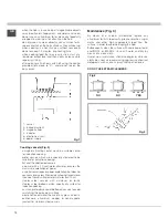
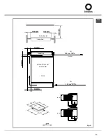
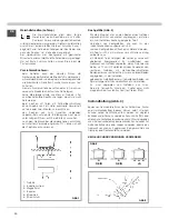
Positioning (Fig. 5)
The fixture is especially designed for fitting into a
worktop as shown in the corresponding figure.
PIace the supplied sealing agent along the hob
perimeter.
Do not install the hob over an oven; incase you do,
make sure of the following:
- the oven is equipped with an appopriate cooling system
- there isno warm-air Ieakage from the oven to wards the hob
- suitabIe air-inIets are provided as shown in the figure.
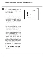
Electrical connection (Fig. 6)
Prior to carrying out the eIectrical connection, please
ensure that:
- the plant characteristics are such as to follow what is
indicated on the matrix plate placed atthe bottom of
the working area;
- that the plant is fitted with an efficient earth connection,
folIowing the standards and law provisions in force. The
earth connection is compulsory interrns of the law.
Should there beno cable and/or plug on the equipment, use
suitable absorption material for the working temperature as
well, as indicated on the matrix plate. Under no circumstance
must the cable reach a temperature above 50°C of the
ambient temnerature.
If connecting directly to the mains power supply, fita multi-
poie switch ofa suitable size for the rated capacity with a
clearance distance which completely disconnects the power
line under over voltage category III conditions, consistently
with the rules of installation (the yellow/green earth wir must
not be interrupted). The plug or omnipolar switch must be
easily reached on the installed equipment.
N.B.:
The manufacturers decline any responsibility in the
event of non-compliance with what is described above and
the accident prevention norms not being respected and
followed.
To avoid all risk, if the power cable becomes damaged,
it must only be replaced by the manufacturer, by an
authorised service centre, or by a qualified electrician.
L
N
230V
~
H05 V2V2–F 3x2.5
Fig.6
Summary of Contents for MIN 32 (L)
Page 1: ......
Page 2: ......
Page 43: ...43 Notes ...
Page 44: ...44 Notes ...
Page 45: ...45 Notes ...
Page 46: ...46 Notes ...
Page 47: ......


