power supplies below.
Phan tom po we ring to stan dard
DIN EN 61938
Correct powering is essential. There have
been various myths and misunderstandings
about it. Authoritative information is con-
tained in the standards documents, but few
people have access to them which is why we
are offering this detailed explanation.
Phantom powering is designed to be ”invis-
ible” and harmless to balanced microphones
which were not specifically designed to use it;
this includes most balanced, professional
dynamic and ribbon microphones, as well as
condenser microphones that use vacuum-tube
circuitry. Exceptions are quite rare. The only
likely cases in which standard phantom power-
ing will endanger a balanced microphone (e.g.
a ribbon) are if a microphone cable, con nector
or adapter is defective or wired in a non-stan-
dard way, such that one modulation lead of the
microphone is shorted to ground at DC while
the powering is on. If a microphone is con-
nected to such a cable with the powering
turned on, impulse current will flow through
its coil or ribbon, possibly causing damage.
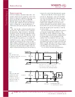
Fig. 1
shows the only valid 48 V and 12 V
phan tom powering circuit (abbreviations: P48
and P12) that can be realized with resistors as
opposed to a center-tapped input transformer.
This illustration is based on the international
standard document EN 61938 of 1997.
The permissible tolerance of the feed resistor
values as such is ±20%. However, the difference
between the resistors of any one pair should
be less than 0.4% (i.e. 27 Ohms for 48-Volt
phantom powering with 6.8 kOhm). This
close matching is necessary to maintain ade-
quate impedance balance for the sake of com-
mon mode rejection. It also avoids the flow of
DC in an input transformer should one be
present, which could lead to distortion or a
reduced dynamic range.
A microphone designed for 48 V phantom
powering could draw as much as 10 mA
according to the standard; a
SCHOEPS
CCM
will draw about 4 mA. This falls well within
the limit set by the prevailing standard. There
are certain commercially available power sup-
plies, preamplifiers, and mixing desks – mostly
older, but some more recent – which fail to
meet this standard and hence may not be able
to power
SCHOEPS
microphones adequately.
If in doubt, equipment should be checked to
verify its suitability for professional work with
SCHOEPS
microphones. On page 7 a method is
described for checking a phantom supply
quickly and easily.
For P12 the standard allows a current of
15 mA. A
SCHOEPS
CCM will draw 8 mA.
Fig. 2
shows a bal an ced but groun ded am -
pli fier in put. In this case eit her a trans for mer
(see fig. 1) or ad di tio nal ca pa ci tors ha ve to be
in ser ted into the au dio li ne.
Unbalanced Operation
Our microphones are intended for balanced
operation such as with the VMS 5 U preampli-
fier from
SCHOEPS
, which is why they should
be operated with balanced inputs. Otherwise
the vulnerability to interference would be
increased. However some equipment only has
unbalanced inputs in which case an unbalanced
input should be balanced with a high-quality
microphone input transformer. This will allow
the signal leads from the microphone to be
kept balanced, for best rejection of interference.
If such an arrangement is not possible, how-
ever, a CCM microphone may be operated in
unbalanced mode by taking the signal from
pin 2 via a coupling condenser with a value as
shown in Figure 2 above. The signal from pin 3
should be left unconnected; do not short it to
ground. This ”unbalancing act” must occur
between the power supply and the preampli-
fier input, however, since naturally all three
pins of the microphone must still connect to
its phantom or parallel power supply.
Simultaneous Connection to Multiple Inputs
If a microphone has to be connected to multi-
ple inputs simultaneously, an active micro phone
splitter should be used in order to preserve
the loading and powering conditions for the
SCHOEPS
GmbH · Spitalstr. 20 · D-76227 Karlsruhe (Durlach) · Tel: +49 (0)721 943 20-0 · Fax: +49 (0)721 943 2050
www.schoeps.de · [email protected]
Phantom Powering (continued)
5
Technology

