Schmidt 506690 Instructions For Use Manual Download Page 9

Instructions for Use 

– SCHMIDT

®

 Flow sensor SS 20.260 

Page 9


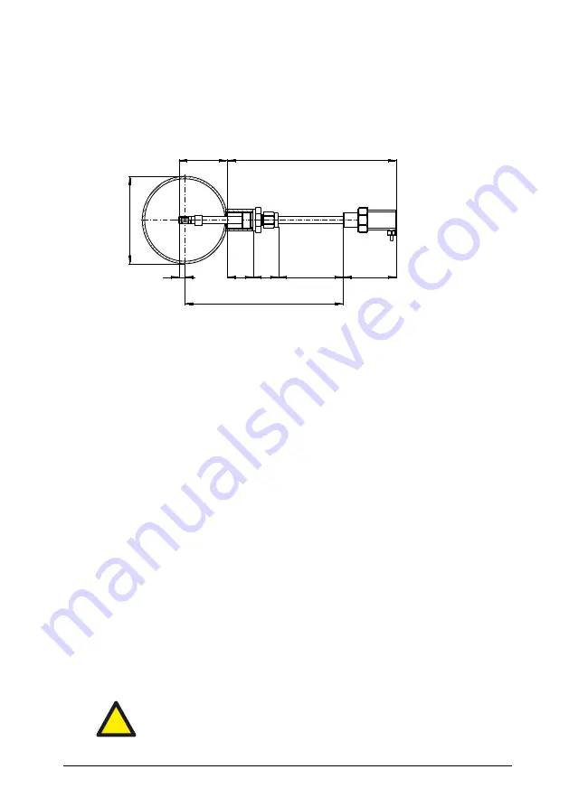
Mounting with a through-bolt joint 

The  sensor  is  installed  using  a  special  through-bolt  joint  (517206).  Nor-
mally, a sleeve is welded as a connecting piece onto a bore in the medium-
guiding pipe, in which the external thread (G½) of the through-bolt joint is 
screwed (see Figure 3). 


Figure 3 


Sensor length [mm] 

D

A


Outer diameter of the pipe [mm] 

SL 

Length of the weld-in sleeve [mm] 

Sensor tube setting length [mm] 

AL


Projecting length [mm] 

MID 

Minimum immersion depth [mm] 


Bore a mounting opening in a pipe wall. 


Weld connecting piece with an internal thread G½ resp. Rp½ centered 
above the mounting opening of the pipe. 
Recommended length of sleeve: 

15 ... 40 mm 


If  necessary  wrap  thread  of  through-bolt  joint  with  common  sealing 
tape, for example made of PTFE. 


Screw thread of through-bolt joint by hand into connecting piece then 
tighten it firmly with a fork wrench (SW27). 


Remove spigot nut of through-bolt joint and extract both seal halves. 


Remove protective cap from sensor tip and attach spigot nut on sen-
sor probe. 


Insert probe in threaded part of through-bolt joint, attach seal halves 
and screw on spigot nut manually to such an extent that  the sensor 
probe can be inserted without jamming. 


In  case  of  a  longer  sensor  probe  push  it  partly  into  the  pipe  as  re-
quired. 


Always avoid bending of the probe tube during screwing. 

L

AL

66

SL

32


MET=20

8

E

D

A

!

MID = 20 


Summary of Contents for 506690

Page 1: ...SCHMIDT Flow Sensor SS 20 260 Instructions for Use ...

Page 2: ... 2 Application range 4 3 Mounting instructions 4 4 Electrical connection 11 5 Signalization 12 6 Startup 14 7 Information concerning operation 15 8 Service information 16 9 Technical data 18 10 Declaration of conformity 19 Imprint Copyright 2020 SCHMIDT Technology GmbH All rights reserved Version 508981 02H Subject to modifications ...

Page 3: ...tions described in these instruc tions for use will forfeit any warranty and exclude any liability The unit is designed exclusively for the use described below see chapter 2 In particular it is not designed for direct or indirect protec tion of personal or machinery SCHMIDT Technology cannot give any warranty as to its suitability for certain purpose and cannot be held liable for accidental or seq...

Page 4: ... precision instrument with high measuring sensitivity In spite of the robust construction of the sensor tip soiling of the inner sen sor elements can lead to distortion of measurement results see also chap ter 8 During procedures that could yield soiling like transport mounting or dismounting of the sensor it is recommended to place the enclosed SCHMIDT Technology protective cap on the sensor tip ...

Page 5: ...lways position the sensor head if possible in the middle of the pipe or shaft Installation with low disturbance Local turbulences of the medium can cause distortion of measurement results Therefore appropriate mounting conditions must be guaranteed to ensure that the gas flow is supplied to the sensor in a quiet state and low in turbulence in order to maintain the accuracy specified see chapter 9 ...

Page 6: ...it is not pos sible to observe the specified abatement distances increased deviations of the measurement results are to be expected or it is necessary to take additional measures4 The profile factors specified in Table 2 may become void by the use of flow rectifiers Calculation of volume flow If the cross section area of the pipe is known the output signal of the flow speed wN can be used to calcu...

Page 7: ... 0 817 10 4 130 1 040 2 599 180 182 5 0 825 15 5 194 1 554 3 885 200 200 8 206 5 0 829 20 0 250 1 999 4 998 250 10 260 4 0 835 32 0 400 3 202 8 004 300 300 12 309 7 0 840 45 6 570 4 556 11 390 350 14 339 6 0 842 54 9 686 5 491 13 728 400 400 16 389 0 845 72 2 903 7 223 18 058 450 450 18 437 0 847 91 5 1 143 9 147 22 867 500 500 20 486 0 850 114 1 419 11 353 28 383 600 600 24 585 0 854 165 2 066 16...

Page 8: ...ion depth in this case and this method requires access from both sides for operation Drill a bore in the wall with 13 14 mm diameter Carefully insert measuring probe with an attached protection sleeve into the bore so that the mounting block of the enclosure is in contact with the wall Screw on the enclosed fastening nut by hand on the medium side turn sensor into required position and tighten fas...

Page 9: ...ead G resp Rp centered above the mounting opening of the pipe Recommended length of sleeve 15 40 mm If necessary wrap thread of through bolt joint with common sealing tape for example made of PTFE Screw thread of through bolt joint by hand into connecting piece then tighten it firmly with a fork wrench SW27 Remove spigot nut of through bolt joint and extract both seal halves Remove protective cap ...

Page 10: ...angular position carefully for example by means of a spirit level at the octagonal part of the sensor enclosure Angular deviation should not be greater than 3 relative to the ideal measuring direction Otherwise the measurement accuracy may be affected In case of wrong adjustment the through bolt joint has to be loosened and the alignment procedure must be repeated Mounting accessories Type art no ...

Page 11: ... 10 It is protected against a polarity reversal typical operating current is 40 mA at maximum 60 mA7 Only operate sensor within the defined range of operating volt age 24 V DC 10 Undervoltage may result in malfunction overvoltage may lead to irreversible damage to the sensor The specifications for the operating voltage are valid for the internal con nection of the sensor Voltage drops generated du...

Page 12: ...ted to a maximum of 10 nF 5 Signalization Light emitting diodes The sensor is equipped with 2 light emitting diodes LED indicating its functional state Figure 5 Operating state LED 1 LED 2 Supply voltage none wrong polarity too low Sensor ready for operation Supply voltage beyond specification range or Medium temperature beyond specification range Sensor defective Table 5 LED off LED flashes appro...

Page 13: ...nstant Voltage output wN Current interface wN 𝑤𝑁 𝑤𝑁 𝑚𝑎𝑥 10 𝑉 𝑈𝑂𝑢𝑡 𝑤𝑁 𝑤𝑁 𝑤𝑁 𝑚𝑎𝑥 16 𝑚𝐴 𝐼𝑂𝑢𝑡 𝑤𝑁 4 𝑚𝐴 Figure 6 Representation for flow velocity Representation of medium temperature The measuring range of the medium temperature is 20 to 120 C Figure 7 Falling below this temperature is still output in a linear way down to 30 C 3 mA going deeper the signal remains constant An exceeded temperature is outp...

Page 14: ...ing of the fastening screw of the through bolt joint Correct electrical connection in the field switch cabinet or similar Prior to startup the sensor check mounting and electrical con nection Five seconds after switch on the sensor is ready for operation If the sen sor has another temperature than the ambient this time is prolonged until the sensor has reached its ambient temperature If the sensor...

Page 15: ...le connected cor rectly Supply voltage connected to control Supply cable broken Power supply unit large enough IwN ITM 0 mA Sensor element defective Send in sensor for repair IwN ITM 2 mA Operating voltage beyond specifi cation range too low high Medium temperature beyond spec ification range too low high Check operating voltage and set it correctly Check medium temperature and set it correctly Iw...

Page 16: ...tem During manual cleaning proceed with great care In case of persistent deposits the sensor chip as well as the interior of the chamber head can be cleaned carefully by using residue free drying alco hol e g isopropyl alcohol or soapy water with special cotton swabs Figure 8 Suitable cotton swabs with small cleaning pads For this purpose cotton swabs that have small soft cotton pads are suita ble...

Page 17: ...f the sensor Before transport or shipment of the sensor the delivered protective cap must be placed onto the sensor tip Avoid soiling or mechanical stress Calibration If the customer has made no other provisions we recommend repeating the calibration at a 12 month interval To do so the sensor must be sent in to the manufacturer Spare parts or repair No spare parts are available since a repair is o...

Page 18: ...120 C 0 70 C Humidity range 0 95 rel humidity RH non condensing Operating pressure Atmospheric 700 1 300 mbar Operating voltage UB 24 VDC 10 reverse voltage protected Current consumption Typ 40 mA 60 mA max Analog outputs Voltage output Current output Maximum load capacity 1 or 2 pcs short circuit protected 0 10 V RL 10 k 4 20 mA RL 300 10 nF Electrical connection Non detachable connecting cable p...

Page 19: ...Instructions for Use SCHMIDT Flow sensor SS 20 260 Page 19 10 Declaration of conformity ...

Page 20: ...r Use SCHMIDT Flow sensor SS 20 260 Page 20 SCHMIDT Technology GmbH Feldbergstraße 1 78112 St Georgen Germany Phone 49 0 7724 899 0 Fax 49 0 7724 899 101 Email sensors schmidttechnology de URL www schmidt sensors com ...

Reviews: