4
Operating instructions
Safety-monitoring module
SRB-E-212ST / SRB-E-322ST
EN
2.6 Safety classification
2.6.1 Safety classification of semi-conductor output
Standards:
ISO 13849-1, IEC 61508, IEC 62061
PL:
e
Control Category:
4
PFH
D
:
≤ 2.66 x 10
-9
/ h
PFD
avg
:
≤ 2.42 x 10
-5
SIL:
suitable for SIL 3 applications
Service life:
20 years
2.6.2 Classification of relay output
Standards:
ISO 13849-1, IEC 61508, IEC 62061
PL:
e
Control Category:
4
DC:
high
CCF:
> 65 points
PFH
D
:
≤ 1.25 x 10
-8
/ h
PFD
avg
:
≤ 5.3 x 10
-5
SIL:
suitable for SIL 3 applications
Service life:
20 years
The PFH value of 1.25 × 10
-8
/h applies to the combinations of contact
load (current through enabling contacts) and number of switching
cycles (n
op/y
) mentioned in the table below. At 365 operating days per
year and a 24-hours operation, this results in the below-mentioned
switching cycle times (t
cycle
) for the relay contacts.
Diverging applications upon request.
Contact load
n
op/y
t
cycle
20 %
880,000
0.6 min
40 %
330,000
1.6 min
60 %
110,000
5.0 min
80 %
44,000
12.0 min
100 %
17,600
30.0 min
3. Mounting
3.1 General mounting instructions
Mounting: snaps onto standard DIN rails to EN 60715.
Hook bottom of enclosure in DIN rail and push down until it engages
in position.
3.2 Dimensions
All measurements in mm.
Device dimensions (H/W/D): 98 x 22.5 x 115 mm
4. Electrical connection
4.1 General information for electrical connection
The electrical connection may only be carried out by
authorised personnel in a de-energised condition.
If mains unit is a new installation or a replacement, the
connector of the output level must be removed and correct
connection of the power supply (A1) must be checked.
To avoid EMC disturbances, the physical ambient and
operational conditions at the place where the product is
installed, must meet the provisions laid down in the paragraph
"Electromagnetic Compatibility (EMC)" of EN 60204-1.
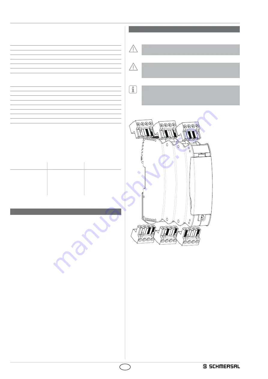
4.2 Coding of connecting terminals


