schmersal SRB 202MSK Operating Instructions Manual Download Page 7

7

SRB 202MSK /

SRB 202MSK/QS

Operating instructions
Safety-monitoring module

EN

8.2 

Sensor coniguration

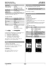
Dual-channel muting circuit (Fig. 14)

• 

Wire breakage and earth leakage in the control circuits are detected.

• 

The SRB 202MSK/QS detects cross-wire shorts between the muting 
sensors.

• 

With external reset button

• 

The reset button is integrated in the feedback circuit in series.

• 

If the reset button is not required, establish a bridge.

• 

Control category 4 – PL “e” to DIN EN ISO 13849-1 possible

Master reset (Fig. 15)

• 

The master reset pushbutton must be connected to terminal X1-MR.

• 

The master reset enables resetting a locked safety-monitoring module. 
The input MR reacts on a rising edge.

S12

S11

S1

K

A

K

B

S22

S21

S2

X2

X1

J

MR

X1

Master-

J

Fig. 14

Fig. 15

8.3 

Actuator coniguration

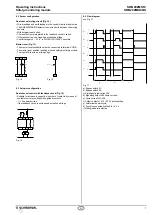
Dual-channel control with feedback circuit (Fig. 16)

• 

Suitable for increase in capacity or number of contacts by means of 
contactors or relays with positive-guided contacts.

• 


S

 = Feedback circuit: 

if the feedback circuit is not required, establish a bridge.

X1

X2

13

23

24

14

K

A

S

L1

N

K

B

K

A

K

B

Fig. 16

8.4  Flow diagram

see Fig. 17

f)

e)

d)

c)

b)

a)

1

1

0

0

1

0

1

0

1

0

t

S

t

S

i)

h)

g)

Fig. 17

a) Bypass switch S1;

b) Bypass switch S2;

c) Simultaneity indication L54;

d) Signalling output L84 (lamp current);

e) Lamp current LA1-LA2;

f) Output contacts 13-14 / 23-24 potential-free;

g) uninterrupted workcycle;

h) Synchronous actuation fault ts > 2.5 s

i) Muting indicator defective

Summary of Contents for SRB 202MSK

Page 1: ...unctions as part of an entire plant or machine It is the responsibility of the manufacturer of a machine or plant to ensure the proper functionality of the entire machinery or plant The safety monitor...

Page 2: ...etermine the Performance Level PL of the entire safety function e g sensor logic actuator to DIN EN ISO 13849 1 an analysis of all relevant components is required 2 4 Technical data General data Stand...

Page 3: ...tandard DIN rails to EN 60715 Snap the bottom of the enclosure slightly tilted forwards in the DIN rail and push up until it latches in position 3 2 Dimensions All measurements in mm Device dimensions...

Page 4: ...ltage 24 VDC on check the proper connection of the SRB 202MSK SRB 202MSK QS and connect a muting lamp to the outputs LA1 and LA2 min 100 mA max 500 mA The enclosure must be opened to set the signallin...

Page 5: ...X2 KB KB F3 F2 Fig 6 SRB 202MSK a Muting sensors b Logic and lamp monitoring K1 K2 K3 F1 A1 L N KA KA K1 K2 K3 KA KB S1 S S2 S4 S3 A2 L54 LA1 LA2 X13 14 13 24 23 X23 b Master J a S11 S12 S13 S21 S22...

Page 6: ...K3 LA SRB 202MSK QS L84 A d K1 K2 K3 Fig 11 SRB 202MSK QS a Muting sensors b Bridge c AOPD semi conductor outputs d Elan safety relay X1 S12 S11 X2 a c 24V b S13 S21 LA1 S22 LA2 S23 X13 14 13 24 23 X...

Page 7: ...locked safety monitoring module The input MR reacts on a rising edge S12 S11 S1 KA KB S22 S21 S2 X2 X1 J MR X1 Master J Fig 14 Fig 15 8 3 Actuator coniguration Dual channel control with feedback circ...

Page 8: ...scription of the safety component Safety monitoring module for muting circuits Harmonised EC Directives 2006 42 EC EC Machinery Directive 2004 108 EC EMC Directive Person authorized for the compilatio...

Reviews: