


4
Operating instructions
Safety-monitoring module
EBW-AZ
EN
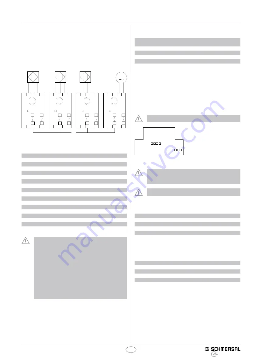
Wiring possibilities (Fig. 3 and 4)
• All commercially available generators with NPN, PNP, NAMUR
and SINUS signals can be connected.
•
An adjustment to the generator type regarded is provided internally
in the device, optionally this can be done in factory or according to
setting instructions.
•
The control command of the relay contacts is not saved, i.e. the
upper or lower limit of the limit value being exceeded causes a
status change of the positive-guided output contacts.
A1
24V
IN
0V
TG
A2
13
14
21
22
14
22
13
21
EBW-AZ-24V
Typ:
DZW
SSW
100%
10%
Rel.
U
B
A1
24V
IN
0V
TG
A2
13
14
21
22
14
22
13
21
EBW-AZ-24V
Typ:
PNP
NPN
b)
NAMUR
a)
DZW
SSW
100%
10%
Rel.
U
B
A1
24V
IN
0V
TG
A2
13
14
21
22
14
22
13
21
EBW-AZ-24V
Typ:
DZW
SSW
100%
10%
Rel.
U
B
A1
24V
IN
0V
TG
A2
13
14
21
22
14
22
13
21
EBW-AZ-24V
Typ:
DZW
SSW
100%
10%
Rel.
U
B
Fig. 3
a) Tacho
b) Potential-free output contacts
Proximity switch PNP
Voltage range:
U
max.
30 VDC (< 4.0 V … > 4.5 V)
Signal load:
approx. 18 mA (at U
B
24 VDC)
Frequency range:
< 100 kHz
Proximity switch NPN
Voltage range:
U
max.
30 VDC (< 4.0 V … > 4.5 V)
Signal load:
approx. 18 mA (at U
B
24 VDC)
Frequency range:
< 100 kHz
NAMUR
Voltage range:
U
max.
30 VDC (< 4.0 V … > 4.5 V)
Signal load:
approx. 9 mA (at U
B
24 VDC)
Frequency range:
< 100 kHz
Tachogenerator
Voltage range:
U
max.
44 VAC (effective)
Signal load:
approx. 9.0 mA (at U
B
44 VAC
eff.
)
Frequency range:
< 100 kHz
"signal recognition" (min.):
approx. 1.44 VAC 4.66 Hz
Fig. 4
Due to the specific design of the EBW devices as standstill
monitor, it must be observed that a control command does
not trigger a restart interlock, i.e. if necessary, a special ON
or RESET signal must be otherwise realised in the electrical
safety circuit, if this is required prior to a restart.
For the definition of the mouvement limit value to be monitored,
the device setting versions furthermore must be observed.
In addition to that, it must be ensured that any incidental or
manipulative alteration of the frontal set-up potentiometer or the
change-over switch of the EBW-AZ devices to EN 292 is preven-
ted or does not lead to a hazardous situation. If the customer is
unable to fulfil this condition, the use of the EBW-WB devices,
which have no external setting devices, is recommended.
Adjustment
In factory or by the customer
Frequency range
PNP/
Namur
NPN
Tacho
Jumper
0.08 … 1 Hz
1
5
9
B4
0.8 … 10 Hz
2
6
10
B3
8 … 100 Hz
3
7
11
B2
80 Hz … 1 kHz
4
8
12
B1
Jumper
1 + 3
2 + 3
4
–
Fig. 5: Type classification
(example: frequency range 8...100Hz, signal generator PNP sensor = type 3)
Opening the enclosure
Necessary to adjust the solder straps located on the circuit board
of the device (Fig. 6).
To this effect, carefully separate the bottom part of the enclosure
from the upper part by means of a suitable tool.
Do not open the device when live!
J1
J2
J3
J4
B1
B2
B3
B4
Fig. 6: lateral view of the left circuit board of the device, programming
by solder straps
When the enclosure is open, the electrostatic discharge
requirements must be respected and observed. After the
setting is completed, the enclosure must be closed again.
Only touch the components after electrical discharge!
Adjust the solder straps J1...J4 to the sensor (Fig. 7)
PNP/Namur
NPN
Tacho
J1
×
J2
×
J3
×
×
J4
×
Fig. 7
Adjust the solder straps B1...B4 to the required frequency
range (Fig. 8)
Hz
Right hinged (approx. 10%) Left hinged (approx. 100%)
B4
0.08 Hz
1 Hz
B3
0.8 Hz
10 Hz
B2
8 Hz
100 Hz
B1
80 Hz
1,000 Hz
Fig. 8