5
BDF 200 AS
Operating instructions
Control panel with emergency stop
EN
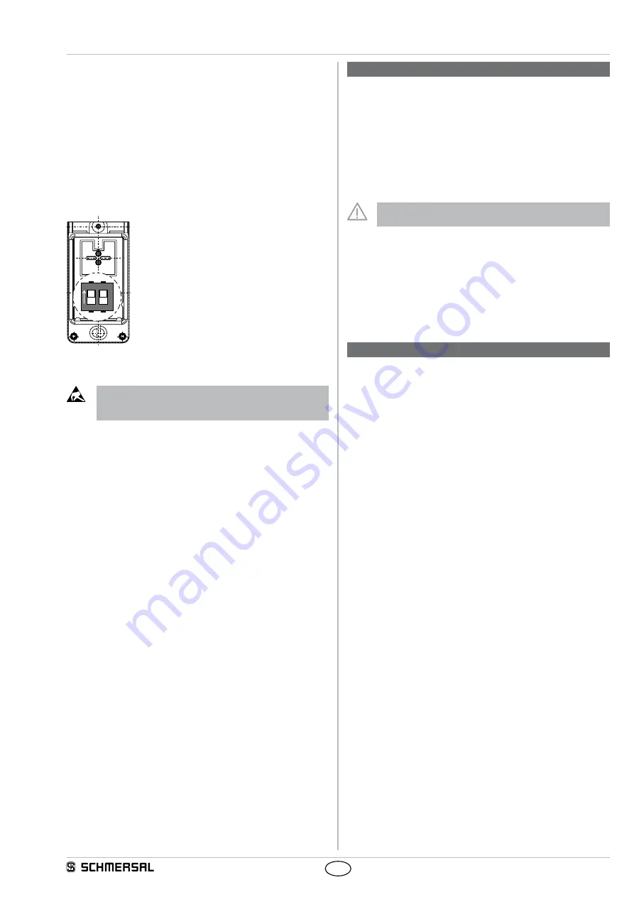
5.5 Programming the slave address
The slave addresses for both integrated
AS-i slaves are programmed through the M12 connector
To that effectn the lower enclosure cover must be opened By means
of the there-located DIP switches, both AS-i slaves can be individually
separated from or connected to the AS-i connection
• DIP-SW 1
AS-i A/B-Slave
• DIP-SW 2
AS-i Safety-Slave
For the AS-i Safety-Slave an address from 1 to 31 and for the AS-i A/B
slave an adress from 1A to 31B can be set by means of an AS-i bus
master or a hand-held programming device
ON
1
2
DIP-SW 1:
AS-i A/B-Slave
DIP-SW 2: AS-i Safety-Slave
Caution!
Do not touch electrostatically loaded elements
Do not touch the printed circuit board
5.6 Status signal "safety release"
The "safety release" status signal from a Safety at Work slave can be
cyclically queried by the control system through the AS-i master To
thiseffect, the 4 input bits with the varying SaW code of a Safety at
Work slave are evaluated through an OR operation with 4 inputs in the
control system
6. Set-up and maintenance
6.1 Functional testing
The safety function of the safety components must be tested The
following conditions must be checked and met:
• Correct fixing of the fitted component
• Check the integrity of the cables and connections
• Check the command and signalling devices for damage
6.2 Maintenance
The function of the emergency stop button must be tested in regular
intervals
Maintenance:
Please observe that the safety function must
be triggered at least once a year to test the system!
In case of correct installation in accordance with the above-described
instructions, the component requires little maintenance Under extreme
conditions, we recommend routine maintenance as follows:
• Check the correct fixing of the control panel
• Remove particles of dust and soiling.
• Check the integrity of the cables and connections
Damaged or defective components must be replaced.
7. Disassembly and disposal
7.1 Disassembly
The safety switchgear must be disassembled in a de-energised
condition only
7.2 Disposal
The safety switchgear must be disposed of in an appropriate manner in
accordance with the national prescriptions and legislations


