


5
AES 1337
Operating instructions
Safety-monitoring module
EN
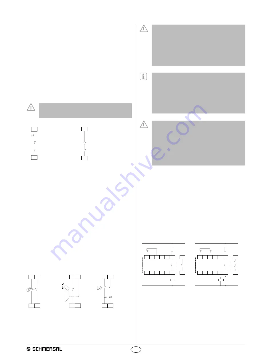
8.2 Start configuration (with edge detection)
External reset button (Fig. 3)
• The external reset button is integrated in the feedback circuit in series.
• The safety-monitoring module is activated upon actuation of the reset
button.
Automatic start (Fig. 4)
• The automatic start is programmed by connecting the feedback circuit
to the terminals X1-X3. If the feedback circuit is not required, establish
a bridge.
•
Caution:
Not admitted without additional measure due to the risk of
gaining access by stepping behind!
• When the AES 1337 safety-monitoring module is used with the
operating mode "Automatic start", an automatic restart after a
shutdown in case of emergency must be prevented by the upstream
control to EN 60204-1 paragraph 9.2.5.4.2.
Due to the operating principle of the electronic fuse, the customer
must check that no hazard is caused by an unexpected restart in
circuits without reset button (automatic reset).
K
A
J
S
K
B
X2
X1
X3
X1
K
A
K
B
Fig. 3
Fig. 4
8.3 Sensor configuration
Dual-channel emergency stop circuit with command devices to
DIN EN ISO 13850 (EN 418) and EN 60947-5-5 (Fig. 5)
• Wire breakage and earth leakage in the control circuits are detected.
• Cross-wire shorts between the control circuits are detected.
• Category 4 – PL e to DIN EN ISO 13849-1 possible.
Dual-channel guard door monitoring circuit with interlocking
device to ISO 14119 (Fig. 6)
• With at least one positive-break position switch
• Wire breakage and earth leakage in the control circuits are detected.
• Cross-wire shorts between the control circuits are detected.
• Category 4 – PL e to DIN EN ISO 13849-1 possible.
Dual-channel control of magnetic safety switches to EN 60947-5-3
(Fig. 7)
• Wire breakage and earth leakage in the control circuits are detected.
• Cross-wire shorts between the monitoring circuits are detected.
• Category 4 – PL e to DIN EN ISO 13849-1 possible.
S22
S21
S14
S13
S22
S21
S14
S13
S22 S14
S21 S13
Fig. 5
Fig. 6
Fig. 7
The connection of magnetic safety switches to the AES
1337 safety-monitoring module is only admitted when the
requirements of the standard EN 60947-5-3 are observed.
As the technical data are regarded, the following minimum
requirements must be met:
– switching capacity: min. 240 mW
– switching voltage: min. 24 VDC
– switching current: min. 10 mA
For example, the following safety sensors meet the
requirements:
– BNS33-11z, BNS33-11z-2063,
BNS33-11zG, BNS33-11zG-2237
– BNS250-11z, BNS250-11zG
– BNS120-11z
– BNS180-11z
– BNS303-11z, BNS303-11zG
– BNS260-11z, BNS260-11zG
When sensors with LED are wired in the control circuit
(protective circuit), the following rated operating voltage must
be observed and respected:
– 24 VDC with a max. tolerance of –5 %/+20 %
– 24 VAC with a max. tolerance of –5 %/+10 %
Otherwise availability problems could occur, especially in
series-wired sensors, where a voltage drop in the control
circuit is triggered by LED's for instance.
8.4 Actuator configuration
Single-channel control (see Fig. 8)
• Suitable for increase in capacity or number of contacts by means of
contactors or relays with positive-guided contacts.
• If the feedback circuit is not required, establish a bridge.
•
S
= Feedback circuit
Dual-channel control with feedback circuit (Fig. 9)
• Suitable for increase in capacity or number of contacts by means of
contactors or relays with positive-guided contacts.
• If the feedback circuit is not required, establish a bridge.
•
S
= Feedback circuit
X1
X3
13
14
K
A
K
A
K
A
S
L1
N
X1
X3
13
14
K
B
K
A
K
B
K
A
K
B
L1
N
K
A
S
Fig. 8
Fig. 9