Interfaces
EN-US · 30.30.01.02237 · 00 · 04/20
35 / 94
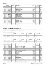
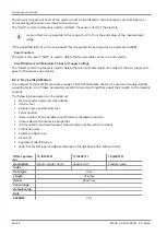
EJECTOR (1–16) EXTENDED VALUES [ro]
(ejectors 1 – 16)
Ejector Extended Values
Bit 7
Bit 6
Bit 5
Bit 4
Bit 3
Bit 2
Bit 1
Bit 0
Bit 0:7
Byte 0:1: System vacuum (in mbar)
Byte 2:3: Air consumption (in l/min)
Byte 4:5: Leakage of last cycle (in mbar/s)
Byte 6:7: Evacuation time T1 (in ms)
Byte 8:9: Last free flow vacuum (in mbar)
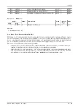
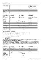
DI MODULES (INPUT)
(DI module 1–6)
DI Module Input
Bit 7
Bit 6
Bit 5
Bit 4
Bit 3
Bit 2
Bit 1
Bit 0
Bit 0:7
DI modules status
Bit 0 = DI module status; Port X1, Pin (2)
Bit 1 = DI module status; Port X1, Pin (4)
Bit 2 = DI module status; Port X2, Pin (2)
Bit 3 = DI module status; Port X2, Pin (4)
Bit 4 = DI module status; Port X3, Pin (2)
Bit 5 = DI module status; Port X3, Pin (4)
Bit 6 = DI module status; Port X4, Pin (2)
Bit 7 = DI module status; Port X4, Pin (4)
5.2.3 Output Process Data
The output process data is used to control the SCTSi, the IO-Link class B master and the individual ejectors
cyclically:
•
To determine the air consumption, the system pressure (> 0 bar) must be preset.
•
All ejectors are controlled via the suction and blow-off commands.
The length of the output process data depends on the design of the compact terminal with respect to the
protocol and number of actual components of the compact terminal. See 5.2 “Process Data”.
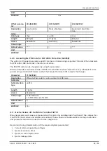
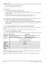
Overview:
PDOut byte
Designation
PDOut byte
Designation
0
Device supply pressure
13
Ejector 13 Control
1
Ejector 1 Control
14
Ejector 14 Control
2
Ejector 2 Control
15
Ejector 15 Control
3
Ejector 3 Control
16
Ejector 16 Control
4
Ejector 4 Control
17 ... 48
Master 1 Port X1 Out-
put
5
Ejector 5 Control
49 ... 80
Master 1 Port X2 Out-
put
6
Ejector 6 Control
81 ... 112
Master 1 Port X3 Out-
put
7
Ejector 7 Control
113 ... 144
Master 1 Port X4 Out-
put


