


IR Security & Safety
575 Birch St., Forestville, Connecticut 06010 / (860) 584-9158 / (860) 584-2136 fax
P/N: M053-016-A
http://www.irsupport.net
Page 11 of 15
2.3
Linking the PIM-485-16-TD-NXT to WAPMs
2.3.1
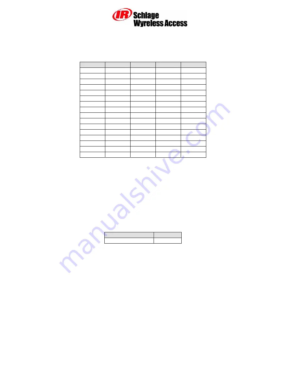
How to Set an RF Channel
One of fifteen RF channels can be set using DIP switch SW7 on the PIM. Table 2-5 shows how to set
SW7 to select the desired RF channel:
Channel
Switch 1
Switch 2
Switch 3
Switch 4
1
up up up Up
1
up up up
down
2
up up
down
Up
3
up up
down
down
4
up down up Up
5
up down up down
6
up down
down Up
7
up down down down
8
down up up Up
9
down up up down
10
down up down Up
11
down up down
down
12
down down up
Up
13
down down up down
14
down down down Up
15
down down down down
Table 2-5 – DIP Switch Setting to Select the RF Channel
NOTE: The first two switch settings select Channel 1.
2.3.2
Linking WAPM’s using the Configuration & Demonstration Tool (CDT)
The Schlage CDT can be used to link WAPM’s to a PIM-485-16-TD-NXT. Refer to the CDT
The PIM-485-16-TD-NXT must be connected to the PC running the CDT using a serial connection
(either RS485 or RS232).
Once the PIM-485-16-TD-NXT is connected to the PC and the CDT is running the Link tab on the
CDT’s PIM panel is used to control the PIM-485-16-TD-NXT’s Link Mode. The Panel field needs to
be set to indicate which WAPM is to be linked. Table 2-6 shows the allowable range of values for the
Panel field on the CDT Link tab.
PIM Model
Panel Field
PIMx-485-16-NEX 0-15
Table 2-6 – CDT Panel Field Range of Values