background image

7

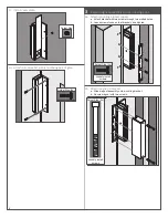
3c  Align magnet to armature.

a.  Press magnet to fully engage with armature.

b.  Mark bracket location.

3d  Remove magnet.

3e  Fully attach bracket.

a.  Check bracket alignment with marks.

b.  Fully tighten two screws in slotted holes.

c.  Drill and tap four (4) remaining holes for #10-24 screws.

d.  Fully tighten all screws.


3f  Reinstall magnet and secure with two screws.

Actual Size (2x)

Loosely install 

screws

For Wiring Installation, see page 8.


L

Note: Some warming of the device under routine operation is 

normal.

Summary of Contents for M490G

Page 1: ...ith the MBS Electrical Specifications Model Amps 12VDC Per Lock Amps 24VDC Per Lock Holding Force lbs Per Lock M490G 0 650 0 350 1500 Warnings and Cautions WARNING Warnings indicate potentially hazardous conditions which if not avoided or corrected may cause death or serious injury Pre Installation Considerations Use ONLY the hardware provided for mounting this product Follow the installation proc...

Page 2: ... wires completely through 4 Flip the housing 180 5 Remove the bolts from both endcaps flip 180 and reinsert into bottom of endcaps NOTE Be careful to not pinch any cables in the bottom endcap with the screw 6 Slide the magnet and bottom endcap into the housing 7 Slide in the top endcap 8 Insert and tighten endcap screws A B ...

Page 3: ... and post surfaces as marked on template b Mark holes and prepare them per template 2 Install magnet assembly to non moving post 2a Attach L Bracket to gate Actual Size 4x 2b Attach mounting bracket to L Bracket Actual Size 4x Actual Size 2x 2c Attach magnet to bracket Actual Size 2x LH ...

Page 4: ...ature bolt must be tightened to 120 in lbs Replace with bolt in Gate kit M490 armature must be disassembled to replace armature bolt WARNING Backing off the bolt after tightening will loosen the thread locking patch which may allow the bolt to loosen over time 3e Attach two TJ brackets together Actual Size 4x Actual Size 3f Align magnet to armature a Close gate b Press magnet to fully engage with ...

Page 5: ... to TJ bracket Actual Size 2x 2b Attach armature plate to armature holder Flat Washer Star Locking Washer Cone Washer Armature Plate TJ Bracket Armature Bolt Actual Size Armature bolt must be tightened to 120 in lbs Replace with bolt in Gate kit M490 armature must be disassembled to replace armature bolt WARNING Backing off the bolt after tightening will loosen the thread locking patch which may a...

Page 6: ...moving post 3a Attach mounting bracket to post a Attach bracket with two screws through two slotted holes b Leave screws loose so that bracket can adjusted Actual Size 2x Loosely install screws 3b Attach magnet to bracket a Slide magnet assembly onto mounting bracket b Secure magnet with two screws Actual Size 2x Loosely install screws ...

Page 7: ...k bracket alignment with marks b Fully tighten two screws in slotted holes c Drill and tap four 4 remaining holes for 10 24 screws d Fully tighten all screws 3f Reinstall magnet and secure with two screws Actual Size 2x Loosely install screws For Wiring Installation see page 8 L L Note Some warming of the device under routine operation is normal ...

Page 8: ... com us Wiring Installation 1 Attach wiring per information shown 24 Volt DC Power Input DC Red Violet Brown DC Black 12 Volt DC Power Input Red DC Violet Brown DC Black DPS 0 25A 30VDC Resistive NO Blue NC Yellow C Green MBS 1A 30VDC Resistive NO Gray C White 2 Connect conduit to lock Z x Conduit ...

Reviews: