2
1
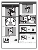
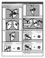
Prepare door using included template.
P519
-043
ND
Seri
es HSLR
"
(3mm)
2¾
" (70
) ba
ckse
t
Conjun
to tra
sero
Distan
ce d
’ent
rée
CL
2
" (54) th
rough
a tra
vés de
à tra
vers
1" (25
)
FOLD ON DOOR EDGE PL
EG
AR PLANTILLA PLIER
G
A
B
ARIT
FOLD ON DOOR EDGE PL
EG
AR PLANTILLA PLIER
G
A
B
ARIT
#8 s
heet
metal
scre
w, 2 p
lace
s
drill
and
tap
as n
eces
sary
#8
tornil
lo de cha
pa, 2
luga
res
per
forar
y toqu
e seg
ún
sea n
eces
ario
#8
vis à
tôle, 2
end
roits
perc
er et
tap
ez si n
éces
saire
Hig
h Ed
ge
Bo
rde
superior
Bord
supé
rieur
Flat (No Bevel)
Plano
Plat
Low Ed
ge
Bo
rde in
ferior
Bord in
férie
ur
1¾"
(44)
door
puer
ta
por
te
CL
CL
" (1
0) th
roug
h, 4 p
lace
s
Drill
half
way
thro
ugh
from
each
side
to en
sure
prop
er lo
catio
n.
" (1
0) a
trav
és d
e, 4
luga
res
Tala
drar
por e
n m
edio
, por
cada
lado
para
aseg
urar
la ub
icac
ión
corre
cta.
" (1
0) à
trave
rs, 4
end
roits
Perc
er d
e part
et d’a
utre de ch
aque
côté
po
ur as
surer
le bon emp
lacement
.
Custo
mer S
ervice
Ser
vicio a
l clien
te S
ervice
à la cli
entèle
1-87
7-67
1-70
11
ww
w.al
legion
.com
/us
Dime
nsio
ns in () a
re in mm.
Dimension
es en
() son en m
m.
Dim
ensions ent
re ()
sont e
n mm.
Instal
lation in
stru
ction
s:
Instru
ccion
es de In
stala
ción:
Instru
ctio
ns d
’instal
lation :
http
s://in
stru
ctions
.alle
gion
.com
/in
str/162
/0
P519-043
ND
Seri
es HSLR
"
(3 mm
)
2¾
" (7
0)
bac
kse
t
Conjun
to t
ras
ero
Dis
tan
ce
d’ent
rée
CL
2
" (54) th
rou
gh
a tr
avé
s de
à tr
ave
rs
1" (
25)
FOLD ON DOOR EDGE PL
EG
AR PLANTILLA PLIER
G
A
B
ARIT
FOLD ON DOOR EDGE PL
EG
AR PLANTILLA PLIER
G
A
B
ARIT
#8
she
et m
eta
l sc
rew
, 2 p
lac
es
dril
l an
d tap
as n
ece
ssary
#8
tornil
lo de cha
pa,
2 l
uga
res
per
for
ar y
toqu
e s
egún
sea n
ece
sar
io
#8 vis à
tôl
e, 2
end
roit
s
per
cer
et t
ape
z si n
éce
ssai
re
Hig
h E
dge
Bo
rde supe
rior
Bo
rd supé
rieur
Flat
(No
Be
vel)
Plano
Plat
Low Ed
ge
Bo
rde
inf
erior
Bo
rd in
fér
ieur
1¾
" (44) door
pue
rta
por
te
CL
CL
" (1
0) th
rou
gh,
4 p
lac
es
Dri
ll h
alf
wa
y th
rou
gh
fro
m e
ach
sid
e
to e
nsu
re p
rop
er l
oca
tio
n.
" (1
0)
a tr
avé
s d
e, 4
lug
are
s
Tal
adr
ar p
or e
n m
edi
o, p
or c
ada
lad
o
pa
ra a
seg
ura
r la
ubi
cac
ión
cor
rec
ta.
" (1
0) à
tra
ver
s, 4 end
roit
s
Per
cer
de
part
et d
’au
tre
de c
haque
côt
é pour
assu
rer
le bo
n e
mp
lac
ement.
Cus
tom
er S
ervi
ce
Se
rvic
io a
l cli
ente
S
ervi
ce à
la c
lien
tèle
1-8
77-
671
-7011
ww
w.al
legion
.com
/us
Dimensi
ons in
() a
re in mm.
Dimension
es en
() s
on en mm.
Dimensions
ent
re ()
sont
en
mm
.
Ins
tal
lation in
stru
ctions:
Ins
tru
cci
one
s de In
sta
lación:
Ins
tru
ctions
d’in
stal
lation :
htt
ps:
//in
stru
ction
s.a
llegion
.com/in
str/
162
/0
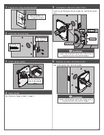
May be installed on
1 3
/4
" thick door ONLY.
2
Install latch into door edge.
Actual Size (2)
Bevel must face
door jamb.
3
Verify chassis position.
Ensure adjustment
plate is tight against
insert.
4
Install cylinder.
See "Install or change cylinder" on page 4.
5
Install exterior plate onto exterior of door.
Latch prongs fit between slide and slide clip. Latch tail fits inside
slide.
slide
latch tail
latch prong
slide clip
WARNING
Continue to hold plate assembly on door. Failure to do so
may cause personal injury and lock damage.
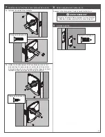
6
Install interior plate onto interior of door.
Place plate against door and hold in place.
WARNING
Continue to hold plate assembly on door. Failure to do so
may cause personal injury and lock damage.


