


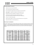


12
ROTARY
MOWER
ASSEMBLY INSTRUCTIONS
1. Remove the mower from the shipping crate.
2. Remove top shield.
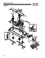
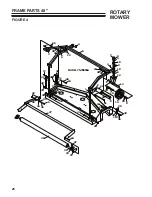
3. Install both left and right hitch arms as shown on page 32, in Figure 7. Torque the 1/2" attaching bolts to
85 ft. lbs.
Install the 1/2" bolt and the 1/2" nut, which holds the two hitch arms together. Torque to 85 ft. lbs.
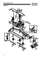
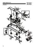
4. Be sure that the mower main drive belt is installed correctly on all pulleys. Check spring-loaded idler arm
position. Choose a mounting hole in the deck which allows the idler arm to lean toward the drive shaft,
with the spring attached. Fasten spring to chain and idler arm as shown on Page 16.
Choose a chain link that stretches spring approximately 1" on 75-70860A or 1-1/2" on 75-70855A &
75-70865A.
5. Check bolts mounting spindles to the deck. Torque should be 35-40 ft. lbs.
6. Check blade bolts. Torque should be 75 - 85 ft. lbs.
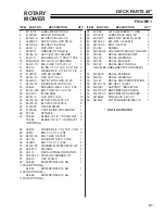
7. Check 1/4" cap screws on pulley bushings for 75-70865A ( page 24 Figure 3, Item 9). Torque should be
95 inch pounds. Tighten these cap screws in alternating sequence 10-12 times to assure equal torque on
all cap screws.
8. Reinstall the top shield.
9. Remove 1/2" locknut on height adjustment lever (located in the hardware bag) and position correctly as
shown for: 75-70855A (page 26, Figure 4)
75-70860A (page 28, Figure 5)
75-70865A (page 30, Figure 6)
10. Remove the drive pulley shield and install the proper drive belt for the power unit. Replace shield.
11. The chute is shipped in the locked position. With the chute brackets in the locked posiiton, attach the
chute to the chute bracket using the hardware located in the hardware as shown for:
75-70855A (page 20, Figure 1, Item 9)
75-70860A (page 22, Figure 2, Item 9)
75-70865A (page 24, Figure 3, Item 9)
Leave the harware loose. Adjust the chute for the best fit against the deck. NOTE: There should be
minimal gaps between the chute and deck, and the chute should hit the deck before the bracket does.
Tighten hardware until bolt heads are partially pulled into the rubber of the chute.
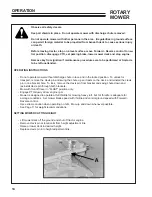
12. Attach mower to power unit. See Page 11 for installation instructions. See Pages 8 & 9 for safety
instructions and Page 14 for operating instructions.


