Operating Manual 90° ACTUSAFE CMF(S)QT
OM-ENGLISH-Failsafe-QT-16xx-V2.00-2022.03.01
2 General
2.7
Protection devices
2.7.1
Torque
ACTUSMART actuators provide electronic torque monitoring.
The switch-off torque can be modified in the controller menu for each direction separately. By default, switch-off torque
is set to the ordered value. If no torque was specified with the order, the actuator is supplied from the factory with the
maximum configurable torque.
For more information, see section 7.2, page 43.
2.7.2
Motor temperature
All ACTUSMART CM actuators are normally equipped with motor winding temperature sensors, which protect the motor
against excessive winding temperature.
The display will show the corresponding error upon exceeding the permissible motor temperature (see section 12.1, page
74).
2.7.3
Input fuse, thermal fuse
The frequency inverter is protected by an input fuse and the explosion-proof version also has a thermal fuse. If one of
these fuses releases, a serious defect accours and the frequency inverter will be disconnected permanent from the power
supply. Then the frequency inverter must be changed.
2.8
Ambient temperature
Unless otherwise specified upon ordering, the following operating temperatures apply:
• On/off duty (open-loop control) -25 . . . +60°C
• Modulating duty (closed-loop control) -25 . . . +60°C
• explosion-proof version -20 . . . +40°C (acc. EN 60079-0)
• explosion-proof version with extended temperature range -40 . . . +60°C
CAUTION:
The maximum operating temperature can also depend on further order-specific components. Please
refer to the technical data sheets to confirm the as-delivered product specifications.
2.9
Delivery condition of the actuators
For each actuator, an inspection report is generated upon final inspection. In particular, this comprises a full visual inspec-
tion, calibration of the torque measurement in connection with an extensive run examination and a functional test of the
micro controllers.
These inspections are conducted and documented according to the quality system and can be made available if necessary.
The basic setting of the end position must be performed after assembly on the actuator.
CAUTION:
Commissioning instructions (see section 5, page 30) must be strictly observed!
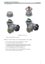
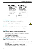
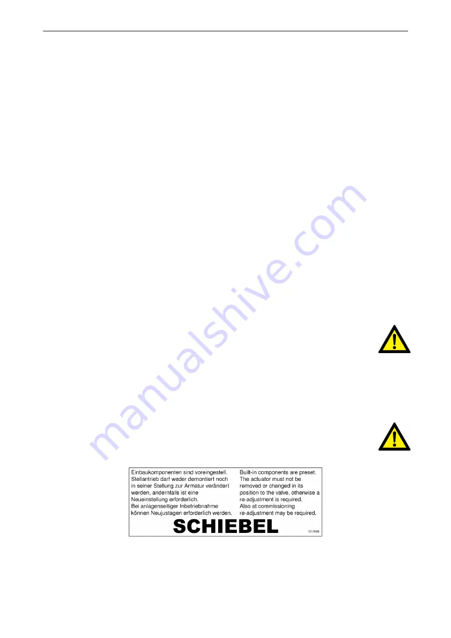
During assembly of the supplied valves at the factory, end postions are set and documented by attaching a
label (see Figure 19). During commissioning at the plant, these settings must be verified.
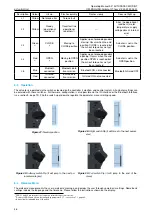
Figure 19:
Label
2.10
Information notice (tag)
Each actuator is provided with a bilingual tag containing key information, which is attached to the handwheel after final
inspection. This tag also shows the internal commission registration number (see Figure 20, page 26).
27

