background image

7

5. Operation

Pic 3

Pic 4

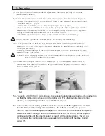
5.1Check that the compressed air details agree with the details given by the turbine

manufacturer (BienAir).

5.2Connect the compressor port of the turbine station (4) to the compressed air system.

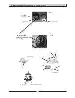
- Connect the suction tub (1) to the extractor hose of the separator (2) (without plastic

adapters see pic. 1 page 4.

- Connect the end of the hose to the side opening of the separator.
- The second hose should be connected to the upper port of the separator (2) and the

extractor/central extractor. The system can be operated by connecting the separator
to any commercially available extractor or central extractor.

- Both of the supplied extractor hoses can be laid and shortened individually.

Caution: Do not lay the hose with excessively small radii; risk of kinking.

5.3- The separator has a check valve, which prevents water from being sucked into the

extractor. The need to empty the separator depends on use and on the intensity of the
cooling water delivery.

- To empty, the two clamps at the top of the separator should be opened and the side

extractor hose (3) removed.
Caution: After emptying ensure that the arrow visible on the lid points to the hose port

attached to the side of the separator.

5.4- To assemble the light head the front sleeve (pic. 3) of the supplied turbine must be

unscrewed  and taken off forward. The light head must be pushed on and screwed
in the reverse order (pic. 4).

!

!

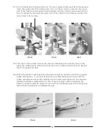
5.5- To use in a SCHICK S3 / S2 milling set, the supplied adapter sleeve must also be pushed on

so that the turbine can be housed in the milling arm. For other manufacturers' milling
devices, corresponding adapters are available on request.

5.6-

.

Instead of the motor milling spindle the turbine provided with the light head is inserted

into the holder on the milling arm from below. The turbine operates at a speed of
300 000 rpm. To avoid temperature-dependent micro cracks in the ceramic the system
works with water cooling. The amount of water necessary for cooling can be adjusted
continuously through the green knurled  screw (6) at the turbine station. The air flow
for atomizing the cooling water can be adjusted at the station with the blue knurled
screw (7)

Summary of Contents for SCHICK ceramic

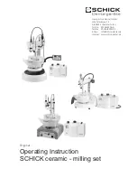
Page 1: ...nstruction SCHICK ceramic milling set Original Georg Schick Dental GmbH Lehenkreuzweg 12 D 88433 Schemmerhofen Telefon 07356 9500 0 Telefax 07356 9500 95 E Mail info schick dental de Internet www schick dental de ...

Page 2: ......

Page 3: ... instead of the turbine By connecting it to the extractor the resulting light grit is transported through the suction tub into the extractor visibility is thus not impaired the workplace remains clean and the harmful grit is eliminated directly where it is produced 2 1 Before using the turbine the manufacturer s instructions for use should be read Check that the details of the air compressor conne...

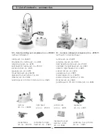
Page 4: ... complete art no 2650 11 without S1 Junior and base turbine art no 2640 1 retaining clip art no 2245 light head for turbine art no 2510 1 controller for light head art no 2480 cable for light head art no 2485 suction tub art no 2470 separator art no 2655 model table art no 2407 9 diamond tool set turbine 1 6 mm 8 items art no 2660 polishing set 2 35 mm 3 items art no 2665 turbine art no 2640 1 sep...

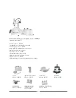
Page 5: ...10 1 suction tub art no 2470 1 separator art no 2655 model table art no 2407 9 diamont tool set turbine 1 6 mm 8 pieces art no 2660 polishing set 2 35 mm 3 pieces art no 2665 turbine art no 2640 1 separator art no 2655 suction tub art no 2470 1 light head for turbine art no 2510 1 diamond tool set turbine 1 6 mm art no 2660 model table art no 2407 9 polishing Set 2 35 mm art no 2665 ...

Page 6: ... 1 Pic 2 1 3 2 4 6 7 5 8 Turbine Standard extractor Separator Suction tub The arrow must point to the side when assembling Suction tub Separator side extractor hose 4 Description Illustration of construction ...

Page 7: ...ty the two clamps at the top of the separator should be opened and the side extractor hose 3 removed Caution After emptying ensure that the arrow visible on the lid points to the hose port attached to the side of the separator 5 4 To assemble the light head the front sleeve pic 3 of the supplied turbine must be unscrewed and taken off forward The light head must be pushed on and screwed in the rev...

Page 8: ...ually to a suitable place on the respective milling device Before securing them the surface beneath must be dry and free from grease and dust 8 9 When the turbine is used bearing lubrication should be carried out with the supplied grease after approx 4 6 hours of operation fig 8 9 Remove the cover from the grease cartridge and insert the cartridge into the clamping mechanism The required quantity ...

Page 9: ... free cloth Do not use aggressive cleaning agents as otherwise the painted surface can be damaged Gross dirt should be removed beforehand with a brush The water separator should likewise be cleaned with a cloth from the inside depending on use This serves particularly to prevent the development of odors and bacterial growth in the container After emptying and or cleaning the water separator ensure...

Page 10: ...onformität des oben bezeichneten Produktes mit den Normen We confirm conformity of the product indicated above with the standards DIN EN ISO 12100 1 DIN EN ISO 12100 2 Schick Dental GmbH Schemmerhofen 31 05 2005 ________________ W Schick Geschäftsführer Managing Director Diese Erklärung ist keine Zusicherung von Eigenschaften im Sinne des Produkthaftungsgesetzes This declaration is not warranty of...

Reviews: