background image

1 About this operating manual 

4


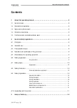
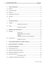
Technical Description............................................................................................... 13


4.1


Overview .................................................................................................................... 13


4.2


Function description .................................................................................................... 13


4.3


Interfaces .................................................................................................................... 13


4.4


Characteristics of the tools .......................................................................................... 14


4.5


Type label ................................................................................................................... 14


14


5


Transport and storage .............................................................................................. 14


5.1


Transport .................................................................................................................... 14


Installation site requirements ............................................................. 14


5.2


Storage ....................................................................................................................... 15


Storage site requirements .................................................................. 15


6


Installation and commissioning .............................................................................. 15


6.1


Installation .................................................................................................................. 15


Required tools .................................................................................... 15


Safety precautions before installation ................................................ 15


Installation .......................................................................................... 15


Installing the control unit on the mounting bracket ............................ 16


6.2


Commissioning ........................................................................................................... 17


Establish power supply ...................................................................... 17


7


Control satellite (optional, not included in delivery) .............................................. 18


8


Power stick (optional, not included) ........................................................................ 18


9


Functions and operation .......................................................................................... 19


9.1


Control units Q3 on / off .............................................................................................. 19


9.2


Operating concept and OLED display ......................................................................... 19


9.3


Operating the handpiece and controller ...................................................................... 20


9.4


Speed control function ................................................................................................ 20


Activating speed control: .................................................................... 21


9.5


Changing the handpiece rotation direction .................................................................. 21


Summary of Contents for 10768

Page 1: ...Instructions Schick GmbH ...

Page 2: ...ade name Serial number Manufacturer Schick GmbH Lehenkreuzweg 12 D 88433 Schemmerhofen Tel 49 7356 95000 Fax 49 7356 950095 info schick dental de www schick dental de www schick industrie de Revision date ...

Page 3: ...reseeable misuse 8 2 4 Selection and qualification of the personnel 9 2 5 Workstations for operating personnel 9 2 6 Safety equipment 9 Fire protection 9 2 7 Safety signs 10 Explanation 10 2 8 Safety measures 10 Personal protective equipment 10 2 9 Safety regulations 10 General information 10 During transport 10 During installation 10 During operation 11 Care and control work 11 Maintenance and re...

Page 4: ...stallation 15 Required tools 15 Safety precautions before installation 15 Installation 15 Installing the control unit on the mounting bracket 16 6 2 Commissioning 17 Establish power supply 17 7 Control satellite optional not included in delivery 18 8 Power stick optional not included 18 9 Functions and operation 19 9 1 Control units Q3 on off 19 9 2 Operating concept and OLED display 19 9 3 Operat...

Page 5: ...tion 24 11 2 Care and inspection plan 24 11 3 Performing care and control work 24 Removal and cleaning of the collet on the Q Basic handpiece 24 Removal and cleaning of the collet on the Q Profi handpiece 25 Removal and cleaning of the collet chuck on the Q Premium handpiece 25 Disassembly of the motor cable on the Q Premium handpiece 26 12 Technical specifications 27 13 Annex 28 13 1 Service addr...

Page 6: ...1 About this operating manual ...

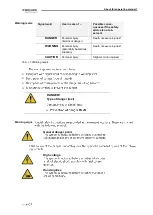
Page 7: ...DANGER Personal injury imminent danger Death or severe injuries WARNING Personal injury potentially hazardous situation Death or severe injuries CAUTION Personal injury Slight or minor injuries Tab 1 1 Warning levels DANGER Type of danger text General danger point High voltage Hand injuries Warning levels Warning signs ...

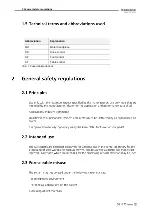
Page 8: ...2 General safety regulations Abbreviation Explanation MH Motor handpiece SK Knee control SF Foot control ST Table control Tab 1 2 used abbreviations ...

Page 9: ...General safety regulations 2 ...

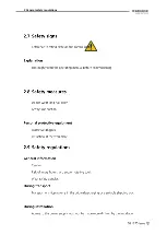
Page 10: ...2 General safety regulations ...

Page 11: ...General safety regulations 2 ...

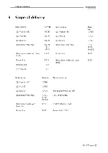
Page 12: ...3 Scope of delivery ...

Page 13: ...Technical Description 4 ...

Page 14: ...0 1st 2nd 3rd 4th 5th 6th 7th 8th 9th 10th ...

Page 15: ...Installation and commissioning 6 ...

Page 16: ...6 Installation and commissioning ...

Page 17: ...Installation and commissioning 6 ...

Page 18: ...7 Control satellite optional not included in delivery ...

Page 19: ...Functions and operation 9 ...

Page 20: ...9 Functions and operation ...

Page 21: ...Functions and operation 9 ...

Page 22: ...10 Troubleshooting ...

Page 23: ...Troubleshooting 10 ...

Page 24: ...e handpiece Interval Care and inspection tasks Remarks Weekly Dismantle the tip and remove dirt Do not use compressed air Once a month Dismantle the collet chuck clean and lubricate Lubricate with Article no 51 1 6642 2 35mm 6643 3 00mm 10219 9323 1 4320 9225 4115 6223 ...

Page 25: ...Care and control tasks for operators 11 ...

Page 26: ...11 Care and control tasks for operators ...

Page 27: ...out cooling Closed system without cooling Drive system Brushless DC motor Brushless DC motor Brushless DC motor Concentricity 0 02 mm 0 02 mm 0 02 mm Collets Ø 2 35 and 3 0 mm optional Ø 2 35 and 3 0 mm optional Ø 2 35 and 3 0 mm op tional Tool change Quick release Quick release Quick release Dimensions Knee device Foot device Table top unit broad 128 mm 175 mm 106 mm height 208 mm 95 mm 200 mm de...

Page 28: ...ithout prior notice Schick GmbH assumes no responsibility for possible errors in this documentation In no event shall Schick GmbH be liable for damages or consequential damages resulting from the use of this documentation or the hardware and software de scribed herein The user is responsible for backing up and updating data Schick GmbH accepts no liability for loss or manipulation of existing data...

Page 29: ...Q3 consists of Q handpiece 10720 9300 9400 3 9400 13 combined with Q3 control unit 10705 10705 1 10705 2 10710 10710 1 10710 2 10715 10715 1 und 10715 2 Foot pedal switch on off 6370 2 Dynamic foot control 9440 ...

Reviews: