background image

ART48 - SPRING

The architecture of ARTHUR’s spring unit reverb offers the best of both worlds: digital delay and analog 

decay. Digital delay provides a simple and efficient solution for delay lines that retard or echo the signal 

before being sent to the spring. However, when it comes to the more complex matter of reverberation, the 

good old spring still provides a more “natural” and musical solution. The spring unit includes six springs to 

give a rich reverb effect that also has a time-adjustable decay.

In addition to its function as an ARTHUR mixer module, the spring unit can also be used as a stand-alone 

unit, providing reverb for a signal from another mixer, or a guitar pedal, for example.

Positioning the spring unit

The spring unit has been configured to sum the signal from the AUX 1 bus. All input units mounted to the 

left of the spring unit will therefore flow to it. On its right side, the spring unit interrupts the AUX 1 bus, so 

the AUX 1 signal from any subsequent input units on this side will be summed by a second spring reverb, 

or by the original AUX 1 master on the L/R Master unit. 

This enables you to create several independent AUX 1 lines. 

As an example, working from the left side of the ARTHUR mixer, you could start by mounting a mic in unit, 

then add a spring unit followed by all the other input and output units. In this particular case, only the first 

mic unit (e.g. for a lead vocal) will benefit from the spring unit’s reverb. All other input units (mounted to the 

right of the spring unit) will be summed through the L/R Master (fig. 1) and will receive their reverb from 

another (external) effects unit. Should you prefer to use the spring unit reverb on all the input units, you 

must mount it right next to the L/R Master, on the left hand side.

Important: If you want to have your spring unit as the final unit on the right side of the mixer - as many users 

prefer - you must first deactivate the summing amp on the L/R Master (fig. 2). This is done by depressing 

the respective blue button (fig. 3) on the L/R Master circuit board, which is positioned just under the fader 

next to the bus connector.

Now let’s take a look at some of this unit’s innovative features.

Fig. 3

Fig. 1

Fig. 2

ANY

 OTHER INPUT

AUX1 to Spring

ANY

 OTHER INPUT

AUX1 to Spring

SPRING

left side of the MASTER

ANY

 OTHER INPUT

AUX1 to MASTER

MASTER

ANY

 OTHER INPUT

AUX1 to Spring

MASTER

ANY

 OTHER INPUT

AUX1 to Spring

SPRING

right side of the MASTER

released

depressed

Summary of Contents for Arthur ART48-SPRING

Page 1: ...ACOUSTIC FIDELITY arthur ART48 SPRING USER MANUAL Assembling instruction on ART48 L Rmast manual ...

Page 2: ...ould result in feedback Larsen effect and ultimate damage to your device Only use the original connection cables if supplied with the device Otherwise this could prove both costly and inconvenient To completely disconnect this device from the AC mains remove the power cable plug from the mains socket When cleaning do not use solvents e g acetone or alcohol These could damage the external finish an...

Page 3: ... safety purpose of the polarized or grounding type plug A polarized plug has two bla des with one wider than the other A grounding type plug has two blades and a third grounding prong The wide blade or the third prong are provided for your safety If the provided plug does not fit into your outlet consult an electrician for replacement of the obsolete outlet 10 Protect the power cord from being wal...

Page 4: ...reate several independent AUX 1 lines As an example working from the left side of the ARTHUR mixer you could start by mounting a mic in unit then add a spring unit followed by all the other input and output units In this particular case only the first mic unit e g for a lead vocal will benefit from the spring unit s reverb All other input units mounted to the right of the spring unit will be summe...

Page 5: ...ngs This effect imitates the room acoustic of a concert hall or church where an instant may pass before you can hear the reflections from the ceiling and walls 100 ms for example The knob labeled 20ms 200ms 4 reacts on the delay time which is adjustable from 20 ms to 200 ms The echo puts a soft echo on the springs imitating a room acoustic with added echo effect such as a big bathroom a car park w...

Page 6: ... the bus When used as a stand alone reverb a power supply PS 12 must be connected directly to the unit s DC In socket 16 The spring unit can receive a signal from two sources the AUX 1 directly from ARTHUR s bus when used together with the ARTHUR mixer or from the external input when used as a stand alone unit The External Input 17 includes a Ext In Gain 18 control knob which can be found under th...

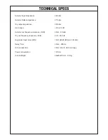
Page 7: ...xternal out frequency response 3dB Dry out frequency response 3dB Equivalent input noise EIN Delay Time Echo repeat time Power consumption Size Weight 48 kohm 270 ohm 300 ohm 8 to 24 dB 50 Hz 50 kHz 5 Hz 50 kHz 102 2 dB 24dB Gain 150 ohm 40 ms 600 ms 40 ms short 690 ms long 120 mA 96x60x475 mm 0 9 kg ...

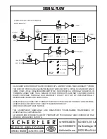
Page 8: ...THEREFORE SCHERTLER SA RESERVES THE RIGHT TO AMEND PRODUCT SPECIFICATIONS WITHOUT NOTICE THE SCHERTLER NAME LOGO ARE REGISTERED TRADE NAMES TRADEMARKS OF SCHERTLER SA SWITZERLAND All SCHERTLER PRODUCTS ARE OF PROPRIETARY TECHNOLOGY AND COVERED BY ONE OF MORE WORLDWIDE PATENTS SIGNAL FLOW EXT IN GAIN EXTERNAL IN AUX 1 DELAY DSP ON OFF DELAY TIME ECHO DSP ON OFF REPEAT TIME SPEED ROOM HALL GLASS WOO...

Reviews: