Operation
P746/EN
OP/G31
MiCOM P746
(OP) 5-
9
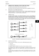
Internal undercurrent signals are available per phase to confirm that each pole has opened.
To maintain the current criterion active while the signal crosses zero, there is a drop-off timer
associated with the pl(t) signal. The latching duration is variable in order to take all cases into
account:
•
Just after the initiation of the CB fail signal, the waveform can include a DC component,
and the time between two successive zero crossings can thus reach one period.
Therefore, the retrip time shall be set long enough for the DC component to have
disappeared so that the time between two successive zero crossings should be close to
one half-period. Moreover it is important to detect the opening of the circuit breaker
quickly because the end of the back trip timer is near. The drop-off duration is therefore
equal to one half 3ms (13ms at 50Hz, 11.3ms at 60Hz).
0
0
T
2T
3T
4T
5T
6T
7T
tps
tss
Tn1=(T/2) + 3ms
(T/2) < t max < T
pl (t)
Tn1 = Switching order
Tp = Trip pole signal
tBF4 - 30ms
P0712ENa
OP
FIGURE 3: CB ELEMENT LOGIC
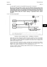
Principle of the undercurrent function.
Instantaneous current measurements are taken for both the positive and negative half
cycles, ensuring immunity to DC offset waveforms, and CT current ring-down.
The two horizontal dotted lines are instantaneous thresholds, fixed in proportion to the user's
I< setting. The instantaneous threshold is at 70 percent of the I< fundamental RMS setting.
As any current rises above the dotted line instantaneous threshold, this rising measurement
triggers a pulse timer to declare that current is flowing. The duration of the pulse is one full
cycle plus 3ms (T+3ms). It does not matter whether the magnitude of the current stays
above the dotted line further, as the detector is effectively edge-triggered. Current flow has
been declared based on this half cycle, and not until the current falls below the detector
setting is the edge-trigger ready to declare an output again. Whilst current is flowing, on the
rise of current in each half-cycle the pulse timer is retriggered. This sequential retriggering
ensures that current is detected.
Summary of Contents for MiCOM P746
Page 4: ......
Page 5: ...Pxxx EN SS G11 SAFETY SECTION...
Page 6: ......
Page 8: ...Pxxx EN SS G11 Page 2 8 Safety Section BLANK PAGE...
Page 16: ...P746 EN IT G31 Introduction MiCOM P746...
Page 18: ...P746 EN IT G31 Introduction IT 1 2 MiCOM P746 IT BLANK PAGE...
Page 26: ...P746 EN TD G31 Technical Data MiCOM P746...
Page 38: ...P746 EN GS G31 Getting Started MiCOM P746...
Page 78: ...P746 EN ST G31 Getting Started MiCOM P746...
Page 80: ...P746 EN ST G31 Settings ST 4 2 MiCOM P746 ST BLANK PAGE...
Page 112: ...P746 EN ST G31 Settings ST 4 34 MiCOM P746 ST BLANK PAGE...
Page 114: ...P746 EN OP G31 Operation MiCOM P746...
Page 136: ...P746 EN OP G31 Operation OP 5 22 MiCOM P746 OP BLANK PAGE...
Page 138: ...P746 EN AP G31 Application Notes MiCOM P746...
Page 142: ...P746 EN AP G31 Application Notes AP 6 4 MiCOM P746 AP BLANK PAGE...
Page 194: ...P746 EN AP G31 Application Notes AP 6 56 MiCOM P746 AP BLANK PAGE...
Page 196: ...P746 EN PL G31 Programmable Logic MiCOM P746...
Page 238: ...P746 EN MR A11 Measurements and Recording MiCOM P746...
Page 240: ...P746 EN MR A11 Measurements and Recording MR 8 2 MiCOM P746 MR BLANK PAGE...
Page 258: ...P746 EN FD G31 Firmware Design MiCOM P746...
Page 280: ......
Page 348: ...P746 EN MT A11 Maintenance MiCOM P746...
Page 350: ...P746 EN MT A11 Maintenance MT 11 2 MiCOM P746 MT BLANK PAGE...
Page 364: ...P746 EN MT A11 Maintenance MT 11 16 MiCOM P746 MT BLANK PAGE...
Page 366: ...P746 EN TS G31 Troubleshooting MiCOM P746...
Page 368: ...P746 EN TS G31 Troubleshooting TS 12 2 MiCOM P746 TS BLANK PAGE...
Page 382: ...P746 EN SC G31 SCADA Communications MiCOM P746...
Page 424: ...P746 EN SC G31 SCADA Communications SC 13 42 MiCOM P746 SC BLANK PAGE...
Page 426: ...P746 EN SG F21 Symbols and Glossary MiCOM P746...
Page 438: ......
Page 440: ...P746 EN IN G31 Installation IN 15 2 MiCOM P746 IN BLANK PAGE...
Page 468: ......
Page 470: ...P746 EN HI G31 Remote HMI HI 16 2 MiCOM P746 HI BLANK PAGE...
Page 500: ...P746 EN HI G31 Remote HMI HI 16 32 MiCOM P746 HI BLANK PAGE...
Page 502: ......
Page 504: ...P746 EN CS A11G31 Cyber Security CS 17 2 MiCOM P746 CS BLANK PAGE...
Page 524: ...P746 EN VH G31 Firmware and Service Manual Version History MiCOM P746...
Page 529: ......


