background image


User Manual, Power contactors, series CT1115/08 and CT1130/08 

Rev. 2.2 

Page 6/26 

Introduction


  CT1000 contactors are air switching components with arc breaking in ce-

ramic. They use a highly sophisticated principle of arc control, combining 

the permanent-magnetic and electro-magnetic blow-out technique.  

This allows practically unrestricted operation for all AC and DC voltages 

and currents within the technical specification.  

  CT1015 contactors are designed for nominal voltages of 1,500 V.  

  CT1030 contactors are designed for nominal voltages of 3,000 V. 

Due to the very high rated insulation voltage CT1030 contactors 

can be used for peak voltages up to 5,000 V. 

  This manual refers to single pole contactors with a conventional 

thermal current of 800 A. For single contactors for 400 A refer to 

manual C20/04-M. For single contactors for 1,100 A refer to man-

ual C20/11-M. 

CT1000  contactors  provide  excellent  switching  performance  from  very 

small up to heavy loads.  

CT1000 contactors are available for vertical and horizontal mounting. 
CT1000 contactors have been designed and tested according to National 

and  International  Railway  Standards.  Due  to  their  unique  features  they 

can also be used in a variety of industrial applications. 
CT1000 contactors offer the following design-related advantages: 

  Compact, rugged design 

   2 voltage levels, several current levels 

  Double-break contacts, cadmium-free contact tips 

  1-, 2- (and 3-) pole versions 

  Easy maintenance: 

o

  Easy inspection of main contact tips, easy replacement of 

main contacts 

o

  Easy replacement of arc chamber (upper module) 

  Drive  system  suitable  for  standard  railway  supply  voltages  and 

tolerances.  No  economy  circuit  required  for  standard  versions. 

Drive systems for industrial applications on demand. 

  Insulation coordination: 

o

  Functional insulation for main circuit 

o

  Basic insulation between main circuit and protective earth 

o

  Reinforced  insulation  between  main  circuit  and  control 

circuit / main circuit and auxiliary circuits 

  Long mechanical and electrical life 

No regular maintenance required. Inspection intervals and exchange of 

wear parts depending on specific application. 


Summary of Contents for CT1115/08

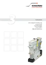
Page 1: ...3 Contactors Contactors CT1115 08 CT1130 08 series Single Pole NO Power Contactors for AC and DC Manual C20 08 M en...

Page 2: ...21 01 2016 div General revision new pictures different way of fixing the ceramic insert introduction of 2 differ ent contact bridge carriers Changes will be implemented step by step be ginning end of...

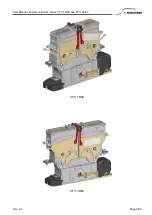
Page 3: ...User Manual Power contactors series CT1115 08 and CT1130 08 Rev 2 2 Page 3 26 CT1115 08 CT1130 08...

Page 4: ...erve the right to make technical alterations without prior notice For updated product information visit www schaltbau gmbh com Furthermore we refer to our General Terms and Conditions of Sale GCS for...

Page 5: ...pments 13 Installation 13 Unpacking and handling 13 Operating position 14 Mechanical requirements 14 Electrical requirements 15 Mechanical installation 15 Electrical installation of the auxiliary swit...

Page 6: ...CT1000 contactors are available for vertical and horizontal mounting CT1000 contactors have been designed and tested according to National and International Railway Standards Due to their unique featu...

Page 7: ...and touch the contactors CT1000 contactors are high voltage switches Getting into contact with conductive parts of the contactors can result in serious injury or even death Active parts are all piece...

Page 8: ...modified EN 60077 2 2003 04 Railway applications Electric equipment for rolling stock Part 2 Electrotechnical components General rules IEC 60077 2 1999 modified EN 50124 1 2010 11 Railway applications...

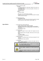
Page 9: ...oltages and tolerances Standard nominal supply voltages are Us 24 V and Us 110 V tolerances from 70 up to 125 of Us Other nominal supply voltages are available on request Double break moving contact b...

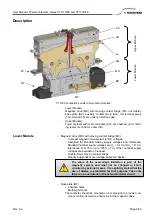
Page 10: ...als FC Press nuts M10 for easy connection of cables Mounting hole 12 7 mm for easy connection of current bars Minimum wire gauges for connecting cables or current bars must be observed Double break co...

Page 11: ...ontactors Typical values Typical pull in time 250 ms Typical drop off time 60 ms Time constant of magnetic drive app 90 ms Settling time for b0 switch up to 10 ms Zero position Off Pull in time On Dro...

Page 12: ...tage 24 24 V 110 110 V Supply voltage tolerance E 30 25 Coil suppression T Suppressor diode Auxiliary contacts 00 1x a1 S870 refer to catalogue D70 1x b0 S870 refer to catalogue D70 M3 screw type term...

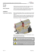
Page 13: ...could indicate damage having occurred during transport impacts bumps falling etc Unpack the contactor and put it on the table in an upright position With one hand press the release buttons on top of...

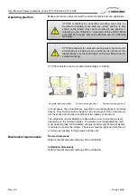
Page 14: ...e nuts must be steel grade 8 8 Schaltbau strongly recommends Schnorr Washers or similar to secure the screws The screws must be tightened with the rat ed torque permissible for the screws and the nuts...

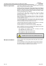
Page 15: ...ve corrosion The minimum gauges for the main terminals and the earth terminal must be observed Schaltbau strongly recommends current bars for the connection of the main terminals with a cross section...

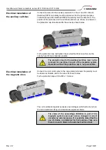
Page 16: ...installation of the magnetic drive Connect the coil control wires to the cage clamp terminals No polarity must be observed Bundle and fix the wires as shown below Fix the protection cap with the M4 x...

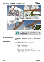
Page 17: ...stallation of the main circuit If you use wires for the connection of the main terminals the cable lugs can be placed on top of the main terminals and tightened with the appropriate screws Schaltbau s...

Page 18: ...al with the appropriate screw Schaltbau strongly recommends a Schnorr Washer or similar to secure the screw Commissioning After installation the following checks are recommended a Check the protective...

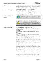
Page 19: ...evaluate the state of the contacts Even after only a few switchings under load the contacts look used and polluted for the inexperienced eye Contacts need only to be replaced if the wear of the contac...

Page 20: ...the contactor with a number 10 socket wrench and put the nut and the washer aside The nut is secured with red locking varnish which will be destroyed during that operation The moving bridge can be pu...

Page 21: ...ching levers must be in the closed position to avoid damage Remove all four M5 screws with a number 8 socket wrench and put the screws and washers aside Two screws are secured with red locking varnish...

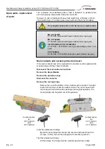
Page 22: ...08 Rev 2 2 Page 22 26 The ceramic protection inserts can be replaced easily by pulling them out of the guidance They only need to be replaced in case of obvious wear Push the replacement insert into...

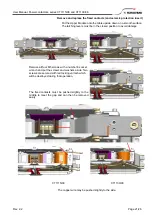
Page 23: ...n Retighten the four M6 screws Torque 7 Nm Check that the cable lug is tight Take special care concerning the correct position of the wires close to the plastic CT1115 08 Take special care concerning...

Page 24: ...of the auxiliary switch subassembly Remove the 2 knurled thumb screws and the 2 Allen head screws M4 Note the mounting position of the subassembly and the individual switches Pull the subassembly out...

Page 25: ...on the bottom of the frame Mount the replace switch in the same mounting position Reassembly of the switch subassembly After all switches have been replaced and the frame has been adjusted to a recta...

Page 26: ...cations Terminal bolts and fuse holders DC emergency disconnect switches Special contactors to suit customer requirements Electrics for rolling stock Equipment for driver s cab Equipment for passenger...

Reviews: